انتقل إلى معلومات المنتج
1 ل 3

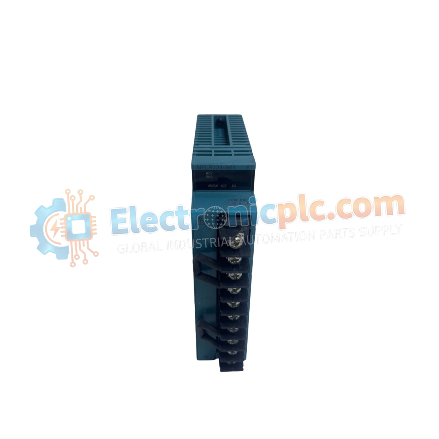
YOKOGAWA NFLR121-S50 S1 Serial Communication Module

YOKOGAWA NFLR121-S50 S1 Serial Communication Module

The YOKOGAWA NFLR121-S50, also cataloged as the NFLR121 Serial Communication Module, serves as a critical interface for integrating subsystem protocols into the STARDOM modular controller platform. It provides high-reliability serial...

15 يشاهد الناس هذا الآن

التوافرفي الأوراق المالية

رمز المنتج: NFLR121-S50 S1
بائع: Yokogawa
Related Series:

الشحن والإرجاع

توصيل موثوق به في جميع أنحاء العالم

  • شركات الشحن: يتم الشحن عبر DHL أو FedEx أو UPS أو USPS .
  • الشحن: تتم معالجة الطلبات خلال يوم عمل واحد إلى يومين، ويتم شحنها خلال 3 إلى 5 أيام عمل .
  • التتبع: يتم توفير تفاصيل التتبع الكاملة عبر البريد الإلكتروني عند الشحن.

ضمان استرداد الأموال خلال 30 يومًا

  • الضمان: فترة إرجاع لمدة 30 يومًا للمنتجات المتوفرة في المخزون والمغلفة من المصنع.
  • الشروط: يجب أن تكون المنتجات غير مفتوحة وغير مستخدمة وفي عبوتها الأصلية.
  • الأصالة: نضمن أن تكون الأجهزة أصلية 100% .

هل تحتاج إلى مزيد من التفاصيل؟ اقرأ سياسة الشحن وسياسة الاسترداد الكاملة.

الأصالة والضمان

  • ضمان أصلي: نحن نوفر فقط قطع غيار أصلية 100%، جديدة تمامًا، ومغلقة من المصنع .
  • تغطية كاملة: كل مكون مدعوم بضمان شامل لمدة 12 شهرًا من تاريخ الشراء.
  • إمكانية التتبع: جميع المنتجات تأتي مع وثائق المصنع الأصلية والملحقات اللازمة للامتثال الكامل للمعايير الصناعية.

الدعم الفني والتوريد

  • مساعدة الخبراء: يقدم فريقنا الفني استشارات مجانية لمساعدتك في التحقق من التوافق مع أنظمة DCS و PLC.
  • مصادر القطع النادرة: متخصصون في المكونات القديمة والتي يصعب العثور عليها من Allen-Bradley و Siemens و ABB و HIMA وغيرها.
  • للاستفسارات المتعلقة بالكميات الكبيرة: تواصلوا معنا على pambo@5gplc.com للحصول على أسعار الكميات الكبيرة أو عروض أسعار المشاريع المخصصة.
عرض تفاصيل المنتج الكاملة

The YOKOGAWA NFLR121-S50, also cataloged as the NFLR121 Serial Communication Module, serves as a critical interface for integrating subsystem protocols into the STARDOM modular controller platform. It provides high-reliability serial data exchange for field-level connectivity.

Hardware Specifications

Parameter Specification
Model NFLR121-S50
Brand YOKOGAWA
Origin Japan
Weight 1.0 kg
Dimensions 130 mm x 50 mm x 30 mm
Operating Temp 0 deg C to 50 deg C
Interface RS-422 / RS-485
Function Subsystem integration (Modbus/Serial)

Modbus Protocol and Subsystem Integration

The NFLR121-S50 acts as a gateway for Modbus RTU/ASCII protocols, enabling the STARDOM controller to interface with diverse third-party field devices, including drives, analyzers, and legacy PLCs. By offloading the serial protocol processing from the main CPU, the module ensures deterministic communication timing. The module architecture is engineered to manage multi-drop network topologies, allowing for dense integration of field assets while maintaining robust error-checking protocols common in high-availability industrial systems.

Frequently Asked Questions

Q: Does the NFLR121-S50 require an external power supply for the RS-485 bus termination?

A: The module does not supply bus power. However, ensure that 120-ohm termination resistors are placed at the physical extremities of the RS-485 bus to prevent signal reflection. External biasing may be required depending on the length of the cable run and the number of connected devices.

Q: How is the module configured for Modbus addressing?

A: Configuration is performed via the STARDOM engineering workstation software. The module maps serial registers to the controller’s global data space, allowing logic programs to read/write to the Modbus device as if it were a local I/O resource.

Field Installation Guidelines

  1. Power down the STARDOM controller base unit before inserting the NFLR121-S50 to prevent damage to the backplane communication pins.
  2. Ensure the module is seated fully into the chassis slots; verify the locking mechanism is engaged to maintain vibration resistance.
  3. Use shielded, twisted-pair cabling for RS-422/RS-485 lines. Connect the shield drain wire to a clean chassis ground at only one end of the bus to prevent ground loops.
  4. Verify communication settings (Baud rate, Parity, Data bits) in the software configuration to match the specifications of the peripheral field devices.
  5. Confirm link health by monitoring the TX/RX status LEDs on the module front panel after initializing the communication port.