قطع غيار أصلية للأتمتة | توصيل سريع عالمي | ضمان لمدة 12 شهرًا — [احصل على عرض سعر]

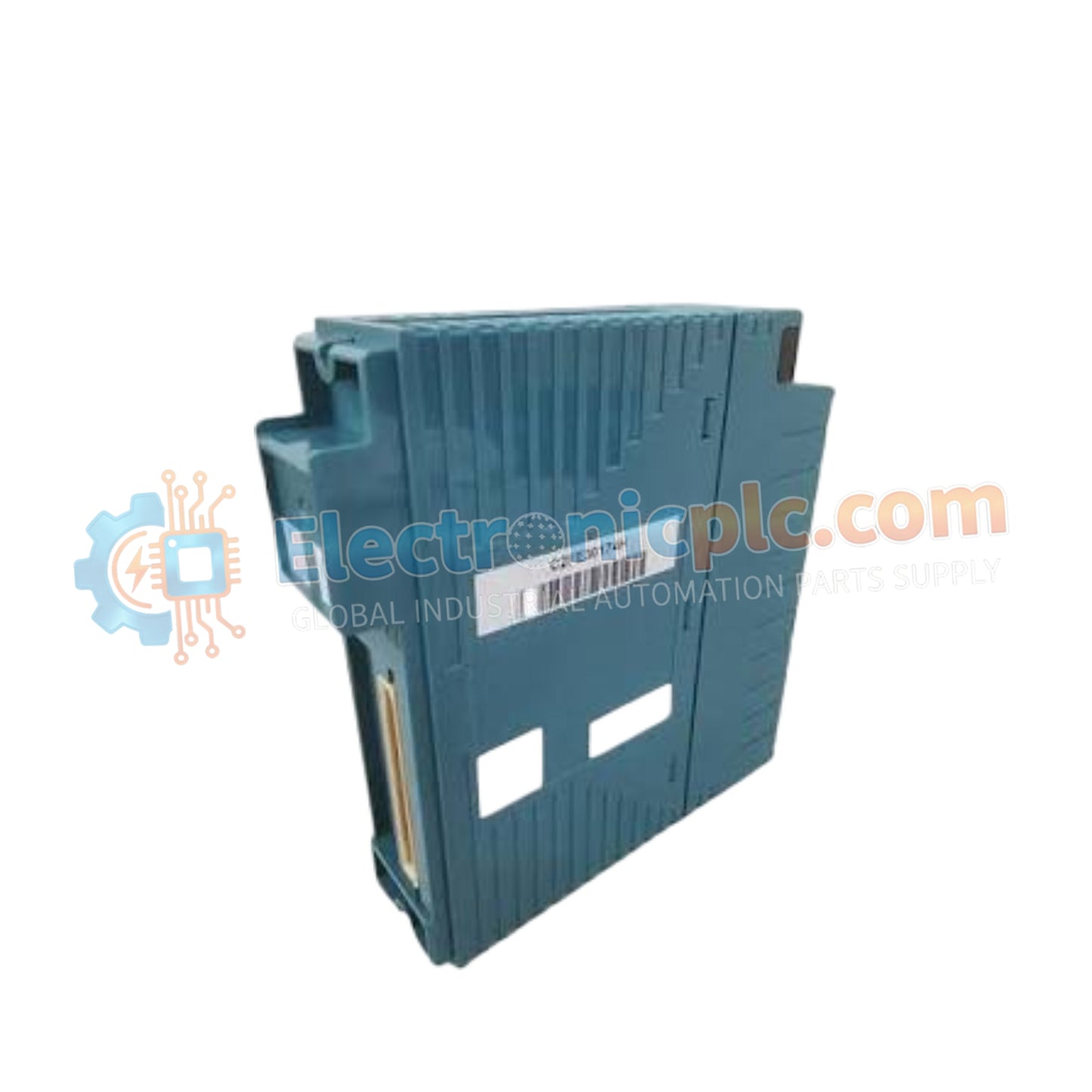
The YOKOGAWA NFSB100-S0/SBT01 (NFSB100 SB Bus Repeat Module) is a specialized hardware component designed for the Yokogawa FCN (Field Control Node) family. It acts as an interface bridge, extending the SB bus (System Bus) connectivity in distributed automation architectures. This module ensures that field control nodes can maintain reliable, high-speed communication even when physical installation distance or system capacity requirements exceed standard limits.
The NFSB100-S0/SBT01 configuration is defined by the following build attributes:
NFSB100: Base model designation for the SB bus repeat module.
-S0: Standard version, indicating base hardware functionality.
/SBT01: Specifies the integration level for the FCN controller bus interface.
| Parameter | Specification |
| Model | NFSB100-S0/SBT01 |
| Brand | Yokogawa |
| Origin | Japan |
| Weight | 0.2 kg |
| Dimensions | 3.2 cm x 12.7 cm x 12.7 cm |
| Function | SB Bus Signal Regeneration/Extension |
| System Compatibility | FCN (Field Control Node) Series |
| Mounting | Controller Rack / DIN Rail |
The NFSB100 functions by regenerating and re-timing the SB bus signals, which effectively compensates for signal attenuation and timing skew over longer cable runs. This is critical for FCN-based systems where deterministic data exchange is required to ensure that control logic and I/O updates remain synchronized across multiple nodes. By maintaining the signal integrity of the SB bus, the module prevents packet loss and communication timeouts, thereby enhancing the overall stability of the control network.
Q: Does the NFSB100-S0/SBT01 require external configuration?
A: The module is designed for "plug-and-play" operation regarding the bus timing. However, system-level software configuration may be required in the FCN controller to register the presence of the extended bus segment and ensure correct I/O mapping.
Q: Is this module capable of galvanic isolation?
A: Yes, the repeater module provides internal isolation between the incoming and outgoing bus segments, which is essential for protecting the controller rack from potential ground potential differences in the field segment.
Power Off: Ensure the FCN node is fully powered down before installing the module to prevent electrical damage to the backplane.
Backplane Seating: Align the module carefully with the rack guides and ensure it is fully engaged with the backplane connectors. Secure it using the integrated retention screws.
Signal Cabling: Use only shielded, twisted-pair cables specified for SB bus communication. Ensure the cable shield is grounded at a single, dedicated instrument earth point to avoid ground loops.
Link Verification: After installation, observe the front-panel status LEDs. A solid "Ready" or "Link" indicator confirms the signal regeneration is active and the bus segment is healthy.
Distance Compliance: Do not exceed the maximum bus segment length defined in the FCN hardware technical manual. Even with a repeater, the cumulative cable length must remain within the specified operational window to guarantee timing accuracy.