سلة التسوق الخاصة بي
0 عنصرًا
قطع غيار أصلية للأتمتة | توصيل سريع عالمي | ضمان لمدة 12 شهرًا — [احصل على عرض سعر]

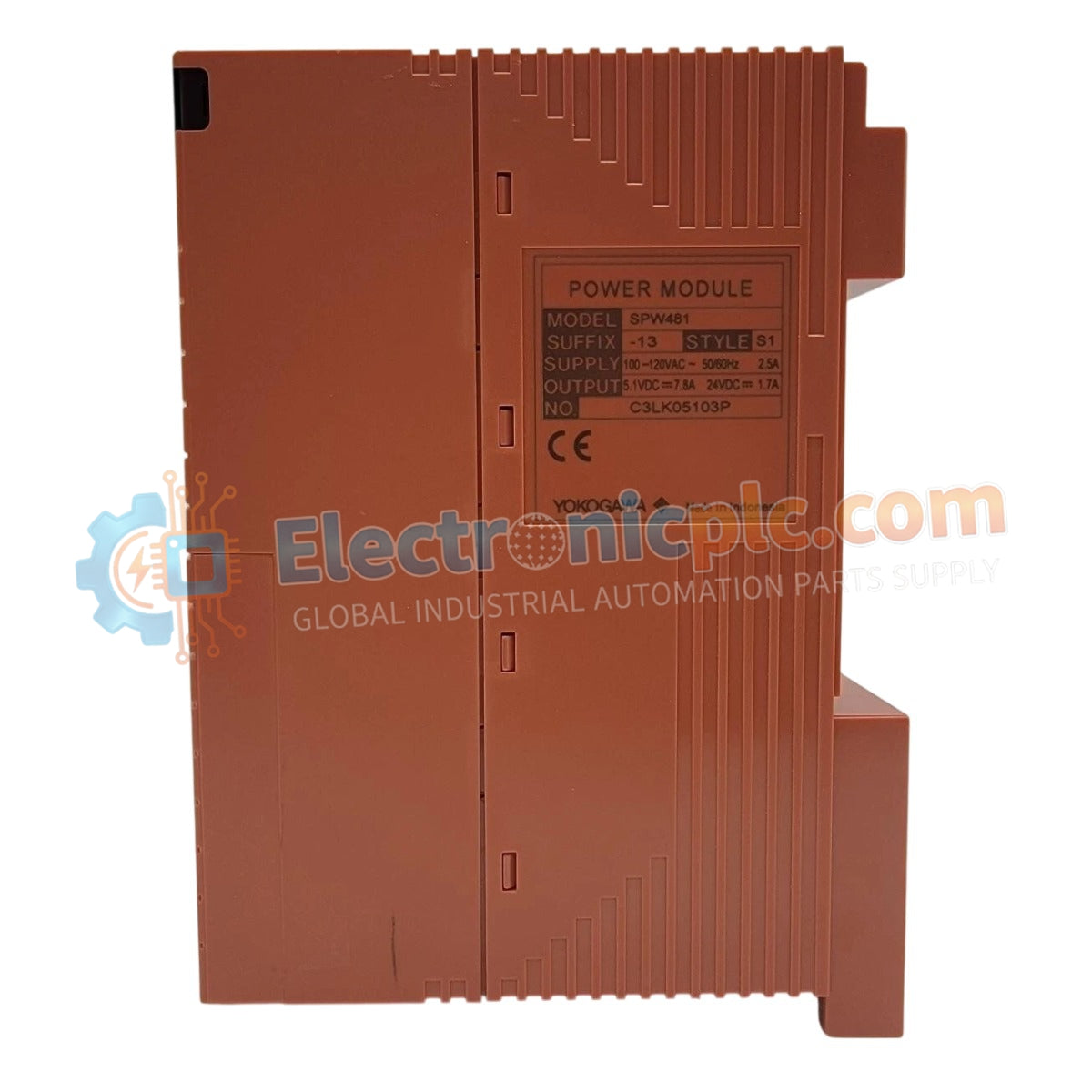
The YOKOGAWA SPW481-13, also cataloged as the SPW481-13 Power Supply Module, operates as a dedicated hardware component for power regulation within DCS process control platforms.
| Parameter | Specification |
| Model | SPW481-13 |
| Brand | YOKOGAWA |
| Origin | JAPAN |
| Weight | 0.9 kg |
| Dimensions | 17.8 cm x 19.1 cm x 19.7 cm |
| Operating Temp | Standard industrial ambient range |
| Power Consumption | Subject to load requirements |
The module integrates specialized circuitry for channel-to-channel isolation and voltage regulation required in DCS instrumentation loops. To maintain consistent output performance, the power supply utilizes internal feedback mechanisms to compensate for input line fluctuations. The output architecture is designed to minimize ripple characteristics, facilitating stable operation for sensitive analog input and output modules within the YOKOGAWA ecosystem. Effective thermal management is required, necessitating adequate cabinet airflow to prevent component derating during continuous operation in high-density rack configurations.
Q: What are the requirements for the physical mounting of this module?
A: The module is designed for standard rack-mount installation. Users must ensure that the module is fully seated into the backplane connector to guarantee proper electrical contact for both power input and signal reference pins.
Q: Can this module be hot-swapped while the system is powered?
A: Hot-swapping capability is dependent on the specific backplane and system controller firmware configuration. Users should consult the system-level installation manual to confirm if the power distribution architecture permits live removal or insertion without affecting the remaining control loops.