سلة التسوق الخاصة بي
0 عنصرًا
قطع غيار أصلية للأتمتة | توصيل سريع عالمي | ضمان لمدة 12 شهرًا — [احصل على عرض سعر]

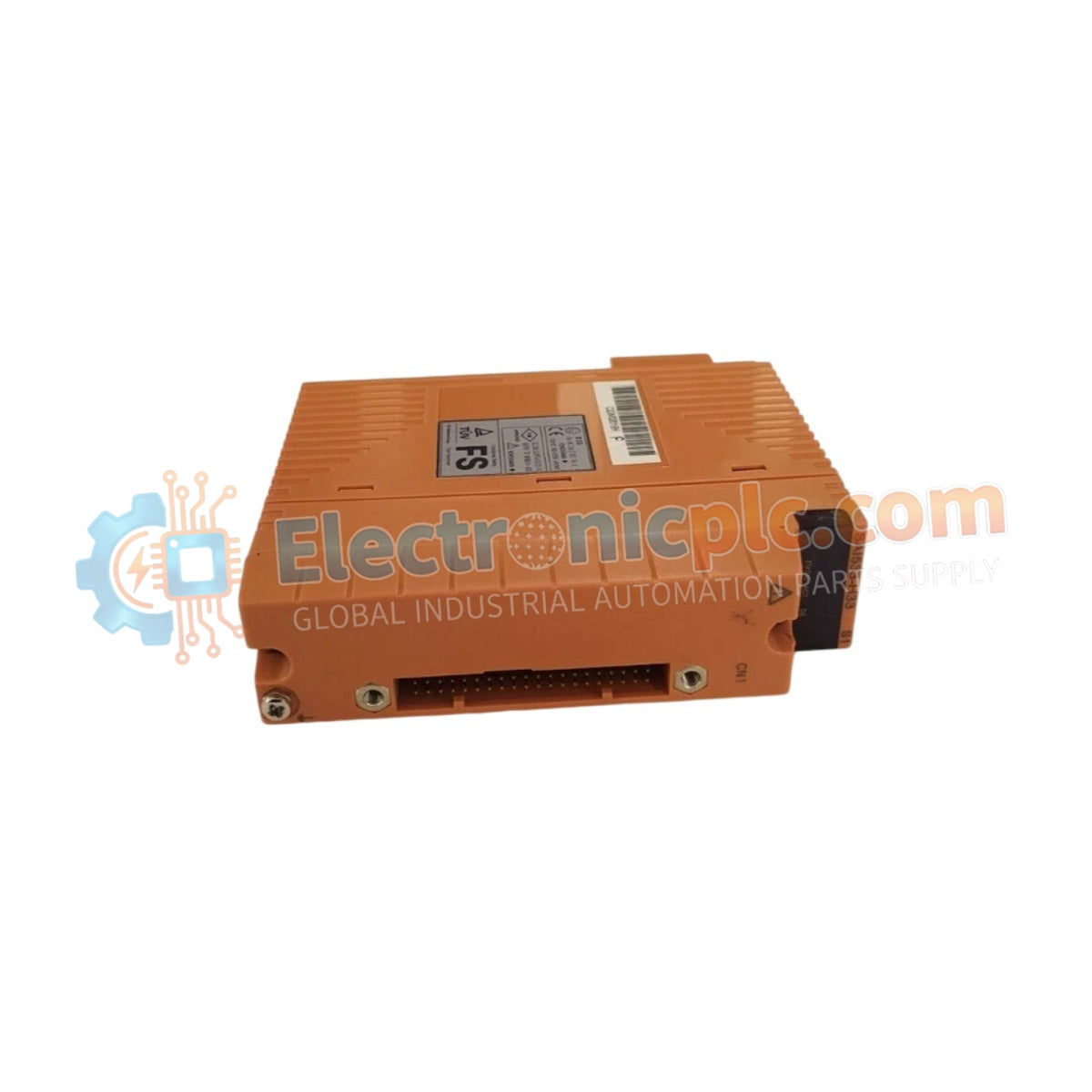
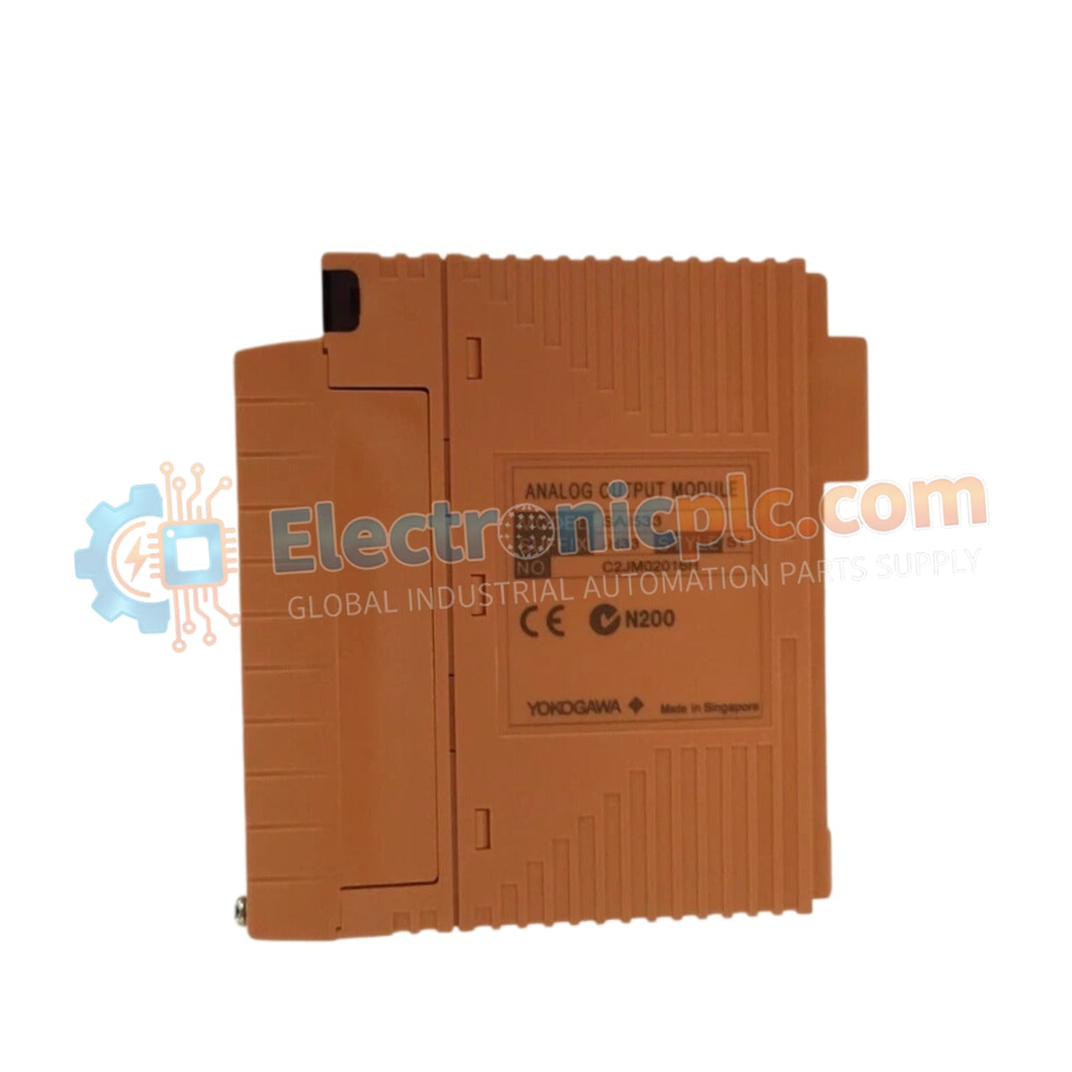
Configured for analog loop signal generation in CENTUM VP control networks, the Yokogawa SAI533-H33 (SAI533-H33 Current Output Module) provides direct physical current-to-field device execution.
| Parameter | Specification |
|---|---|
| Model | SAI533-H33 |
| Brand | Yokogawa |
| Origin | Japan |
| Weight | 0.3 kg |
| Dimensions | 3.2 cm x 10.7 cm x 13 cm |
| Operating Temp | -20 deg C to 70 deg C |
| Power Consumption | 5 VDC, 0.4 A (Internal) |
| Output Range | 4-20 mA |
The SAI533-H33 module integrates channel-to-channel isolation to mitigate ground loops and signal interference between independent field circuits. Each output channel supports standard 4-20 mA analog control loops, ensuring linear current delivery to actuators and positioners. The output circuitry is designed to prevent cross-talk when multiple loops are active simultaneously, maintaining signal accuracy across the full operational range defined by the DCS control logic.
Q: Does the SAI533-H33 support HART protocol communication on its output channels?
A: The SAI533-H33 is a standard current output module. Compatibility with HART protocol overlay depends on the specific hardware revision and system integration; check the module's technical manual to confirm if the output stage supports HART impedance requirements.
Q: What is the maximum load resistance supported by each current output channel?
A: The module is designed to drive standard 4-20 mA loads. The maximum load resistance (R_load) is determined by the output voltage compliance of the module, typically allowing for a load of up to 750 ohms at 20 mA.