انتقل إلى معلومات المنتج
1 ل 3

YOKOGAWA SNB10D-415/CU2T Safety Node Unit

YOKOGAWA SNB10D-415/CU2T Safety Node Unit

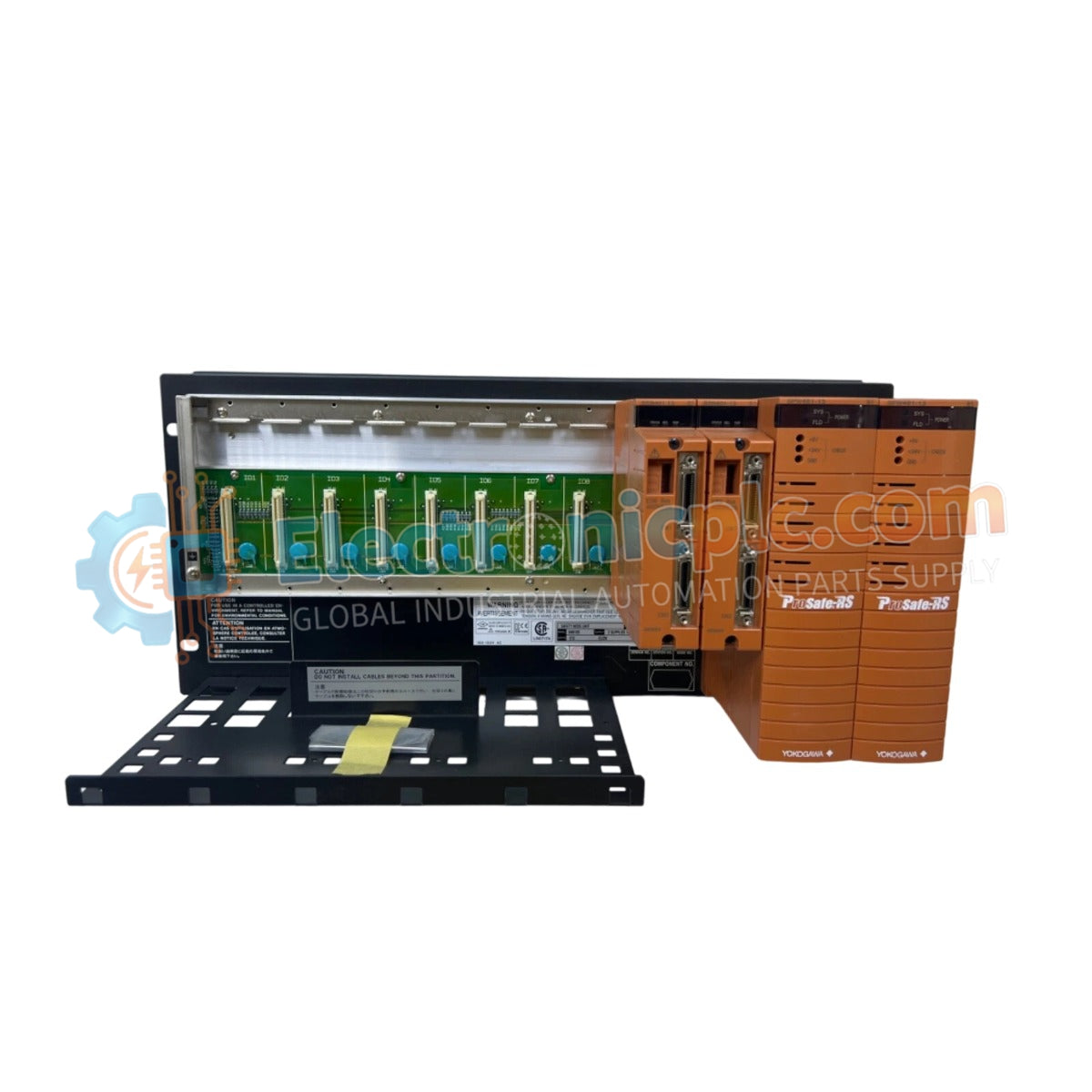
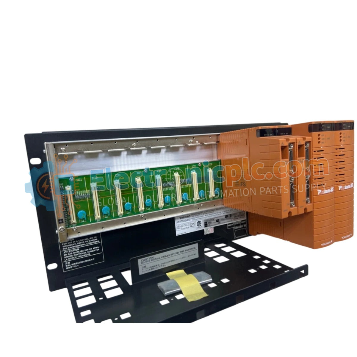
The YOKOGAWA SNB10D-415/CU2T, also cataloged as the SNB10D Safety Node Unit, operates as a dedicated hardware component for field signal interfacing within ProSafe-RS Safety Instrumented System (SIS) platforms.

Hardware Specifications

...
16 يشاهد الناس هذا الآن

التوافرفي الأوراق المالية

رمز المنتج: SNB10D-415/CU2T
بائع: Yokogawa
Related Series:

الشحن والإرجاع

توصيل موثوق به في جميع أنحاء العالم

  • شركات الشحن: يتم الشحن عبر DHL أو FedEx أو UPS أو USPS .
  • الشحن: تتم معالجة الطلبات خلال يوم عمل واحد إلى يومين، ويتم شحنها خلال 3 إلى 5 أيام عمل .
  • التتبع: يتم توفير تفاصيل التتبع الكاملة عبر البريد الإلكتروني عند الشحن.

ضمان استرداد الأموال خلال 30 يومًا

  • الضمان: فترة إرجاع لمدة 30 يومًا للمنتجات المتوفرة في المخزون والمغلفة من المصنع.
  • الشروط: يجب أن تكون المنتجات غير مفتوحة وغير مستخدمة وفي عبوتها الأصلية.
  • الأصالة: نضمن أن تكون الأجهزة أصلية 100% .

هل تحتاج إلى مزيد من التفاصيل؟ اقرأ سياسة الشحن وسياسة الاسترداد الكاملة.

الأصالة والضمان

  • ضمان أصلي: نحن نوفر فقط قطع غيار أصلية 100%، جديدة تمامًا، ومغلقة من المصنع .
  • تغطية كاملة: كل مكون مدعوم بضمان شامل لمدة 12 شهرًا من تاريخ الشراء.
  • إمكانية التتبع: جميع المنتجات تأتي مع وثائق المصنع الأصلية والملحقات اللازمة للامتثال الكامل للمعايير الصناعية.

الدعم الفني والتوريد

  • مساعدة الخبراء: يقدم فريقنا الفني استشارات مجانية لمساعدتك في التحقق من التوافق مع أنظمة DCS و PLC.
  • مصادر القطع النادرة: متخصصون في المكونات القديمة والتي يصعب العثور عليها من Allen-Bradley و Siemens و ABB و HIMA وغيرها.
  • للاستفسارات المتعلقة بالكميات الكبيرة: تواصلوا معنا على pambo@5gplc.com للحصول على أسعار الكميات الكبيرة أو عروض أسعار المشاريع المخصصة.
عرض تفاصيل المنتج الكاملة

The YOKOGAWA SNB10D-415/CU2T, also cataloged as the SNB10D Safety Node Unit, operates as a dedicated hardware component for field signal interfacing within ProSafe-RS Safety Instrumented System (SIS) platforms.

Hardware Specifications

Parameter Specification
Model SNB10D-415/CU2T
Brand YOKOGAWA
Origin Japan
Weight 5.9 kg
Dimensions 482.6 mm x 221.5 mm x 205 mm
Operating Temp 0 deg C to 50 deg C
Power Consumption Not specified (SIS Power Bus)
Compatibility ProSafe-RS SIS
Safety Standard SIL3 compliant (IEC 61508)

Galvanic Isolation and Fail-Safe State Execution

The SNB10D-415/CU2T is architected for SIL3 compliance, providing robust galvanic isolation between field instrumentation circuits and the internal safety control bus. This dual-redundant design ensures that the unit maintains continuous operation in the presence of single-point failures. In the event of a detected logic fault or communication loss with the safety processor, the node is engineered for immediate fail-safe state execution, driving connected valves and actuators to a predetermined safe position to mitigate process risks.

Frequently Asked Questions

Q: Does the unit support hot-swapping of I/O modules during operation?

A: Yes, the SNB10D-415/CU2T supports hot-swapping of individual I/O modules. However, this must be performed in accordance with the site-specific safety procedures and under the condition that the safety controller has transitioned the affected loop to a permissive bypass or maintenance state.

Q: How is the dual-redundant power distribution managed within the rack?

A: The node unit utilizes redundant power input terminals that are diode-ORed to ensure continuous power delivery. The system monitors input voltage health and will trigger a diagnostic alarm via the safety controller if one power feed fails.

Field Installation Guidelines

  1. Mount the unit in a clean, vibration-free environment within a standard 19-inch cabinet, ensuring the ventilation paths are not obstructed.
  2. Terminate all incoming field signal wiring to the dedicated terminal blocks, ensuring that shielding is tied to the chassis ground to prevent electromagnetic interference.
  3. Verify that the dual power supply inputs are connected to independent DC power sources to maintain the redundant architecture.
  4. After hardware installation, conduct a loop check to verify that all analog and contact signals are correctly mapped and reporting to the safety controller.
  5. Ensure the chassis is bonded to the cabinet's protective earth bus using the provided heavy-gauge grounding lug to ensure proper surge protection.