سلة التسوق الخاصة بي
0 عنصرًا
قطع غيار أصلية للأتمتة | توصيل سريع عالمي | ضمان لمدة 12 شهرًا — [احصل على عرض سعر]

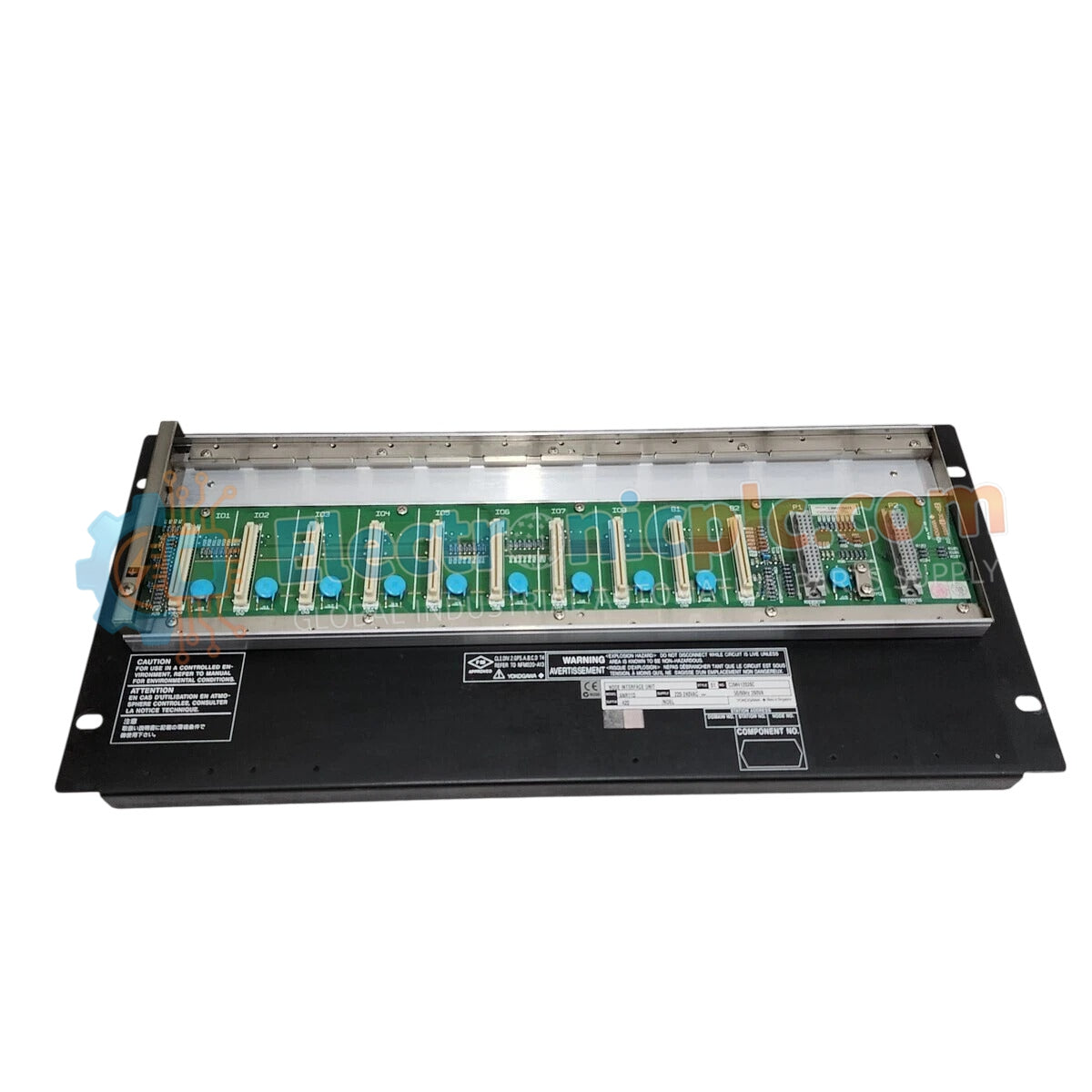
The YOKOGAWA SNB10D-425/CU2N, also cataloged as the SNB10D Safety Node Unit, operates as a dedicated hardware component for signal distribution and I/O bus management within SIS (Safety Instrumented System) platforms.
...التوافر: الكمية المتبقية: 99
توصيل موثوق به في جميع أنحاء العالم
ضمان استرداد الأموال خلال 30 يومًا
هل تحتاج إلى مزيد من التفاصيل؟ اقرأ سياسة الشحن وسياسة الاسترداد الكاملة.

The YOKOGAWA SNB10D-425/CU2N, also cataloged as the SNB10D Safety Node Unit, operates as a dedicated hardware component for signal distribution and I/O bus management within SIS (Safety Instrumented System) platforms.
| Parameter | Specification |
|---|---|
| Model | SNB10D-425/CU2N |
| Brand | YOKOGAWA |
| Origin | JAPAN |
| Weight | 3.52 kg |
| Dimensions | 18.4 cm x 15 cm x 3 cm |
| Operating Temp | Standard Industrial Range |
| Power Consumption | Subject to node configuration |
The SNB10D-425/CU2N facilitates fail-safe state execution within high-integrity safety loops. Designed for use in critical process protection, the unit provides galvanic isolation to prevent fault propagation between safety-critical I/O modules and the communication bus. The hardware is configured to maintain signal integrity during electromagnetic disturbances, ensuring that the 2oo3 (two-out-of-three) voting logic architecture remains stable. This unit serves as the physical interface for safety-rated I/O, ensuring that all signal transitions adhere to predetermined fail-safe protocols in the event of a detected module anomaly.
Q: Does the SNB10D-425/CU2N support hot-swapping in active safety loops?
A: Hot-swapping is prohibited while the safety loop is in an active, energized state. The safety node must be bypassed or the system transitioned to a maintenance state prior to module removal to avoid unintended process trips.
Q: Is the unit compatible with standard field wiring without additional barrier requirements?
A: Compatibility depends on the hazard classification of the field device. If the loop is defined as an intrinsically safe circuit, ensure that external barriers are utilized in accordance with the system design documentation and site safety requirements.


