
سلة التسوق الخاصة بي
0 عنصرًا
قطع غيار أصلية للأتمتة | توصيل سريع عالمي | ضمان لمدة 12 شهرًا — [احصل على عرض سعر]

يعمل YOKOGAWA SNT501-13، والمُفهرَس أيضًا تحت اسم SNT501 Optical ESB Bus Repeater Slave Module، كمكون مادي مخصص لتوسيع نطاقات الاتصال للمدخلات/المخرجات (I/O) ضمن أنظمة CENTUM VP وCENTUM CS 3000. توفر...
التوافر: في الأوراق المالية
توصيل موثوق به في جميع أنحاء العالم
ضمان استرداد الأموال خلال 30 يومًا
هل تحتاج إلى مزيد من التفاصيل؟ اقرأ سياسة الشحن وسياسة الاسترداد الكاملة.


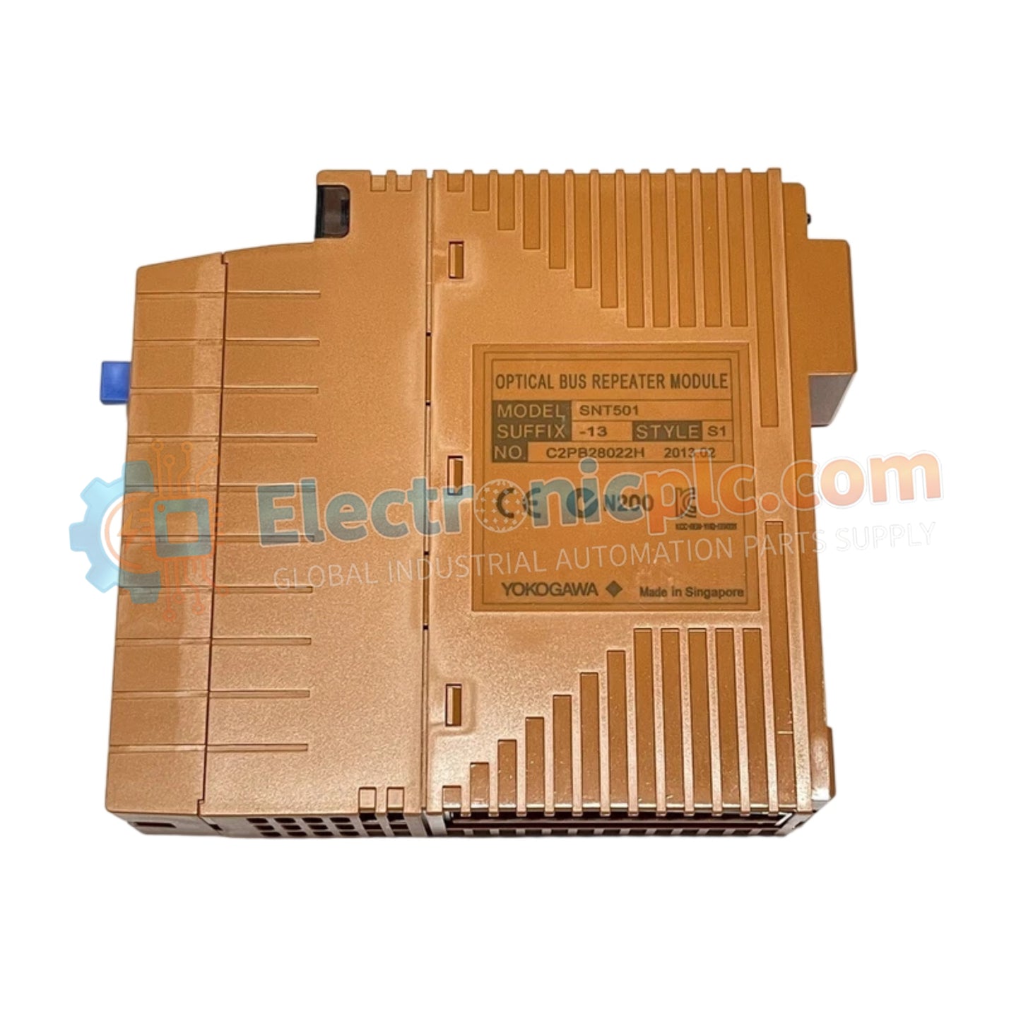
يعمل YOKOGAWA SNT501-13، والمُفهرَس أيضًا تحت اسم SNT501 Optical ESB Bus Repeater Slave Module، كمكون مادي مخصص لتوسيع نطاقات الاتصال للمدخلات/المخرجات (I/O) ضمن أنظمة CENTUM VP وCENTUM CS 3000. توفر هذه الوحدة تنفيذًا ماديًا/كهربائيًا مباشرًا لتحويل الإشارات الضوئية الواردة مرة أخرى إلى إشارات ناقل ESB كهربائية، مما يسهل اتصال عقد الإدخال/الإخراج البعيدة عبر أقسام الألياف البصرية طويلة المدى.
يتم تعريف SNT501-13 بواسطة سمات التكوين التالية:
SNT501: تسمية النموذج الأساسي لوحدة مكرر ناقل ESB البصري التابعة.
1: يشير إلى الإصدار القياسي بدون متطلبات حماية محددة من الانفجار.
3: يحدد واجهة الطرف وتكوين التركيب لوحدة الوحدة الفرعية.
| المعلمة | المواصفات |
| النموذج | SNT501-13 |
| العلامة التجارية | YOKOGAWA |
| المنشأ | اليابان |
| الوزن | 0.2 كجم |
| الأبعاد | 3.2 سم × 12.7 سم × 12.7 سم |
| درجة حرارة التشغيل | المعيار الصناعي |
| استهلاك الطاقة | 5 فولت تيار مستمر (اسمياً) |
| الوظيفة | تحويل الإشارة من ضوئية إلى كهربائية |
تم تصميم SNT501-13 للحفاظ على اتصال حتمي عبر الأجزاء البعيدة من ناقل ESB. من خلال إجراء ترجمة سريعة للإشارة من ضوئية إلى كهربائية، تضمن الوحدة وصول بيانات الحقل إلى وحدة التحكم بالمحطة بأقل قدر من التأخير، مما يدعم متطلبات التوقيت لهندسة التحكم الموزعة. توفر الدوائر الداخلية عزلًا من قناة إلى قناة من جهاز الإرسال والاستقبال البصري، مما يمنع بشكل فعال تداخل الحلقة الأرضية من المساس بسلامة نقل البيانات بين العقد الرئيسية والتابعة.
س: هل SNT501-13 قادر على الاستخدام في تكوين ناقل ESB زائد عن الحاجة؟
ج: نعم، SNT501-13 متوافق مع إعدادات ناقل ESB الزائدة عن الحاجة. عند دمجه كجزء من زوج زائد عن الحاجة، فإنه يوفر تنويعًا للمسار، مما يضمن بقاء الاتصال فعالًا حتى لو تعرض رابط بصري واحد للخطر.
س: هل يمكن تبديل كابل الألياف الضوئية الساخن أثناء اتصال الناقل النشط؟
ج: بينما تم تصميم منطق SNT501-13 للمرونة الصناعية، فإن فصل كابل الألياف الضوئية أثناء التشغيل النشط سيؤدي إلى خطأ في الناقل في وحدة التحكم. تأكد دائمًا من أن النظام في حالة صيانة أو اتبع بروتوكولات النظام المعمول بها قبل إجراء تعديل مادي لروابط الألياف الضوئية.
تأكد من أن موصل الألياف الضوئية نظيف وخالي من الغبار أو الملوثات؛ استخدم مجهر فحص الألياف القياسي الصناعي للتحقق من سلامة وجه الموصل قبل توصيله بـ SNT501-13.
قم بتركيب الوحدة على سكة DIN المخصصة أو موقع الرف، مع ضمان اتصال آمن بدبابيس الطاقة في اللوحة الخلفية.
راقب الحد الأدنى لنصف قطر الانحناء لكابل الألياف الضوئية لمنع توهين الإشارة أو تلف قلب الألياف.
تحقق من أن مؤشر LED لحالة الارتباط البصري يؤكد اتصالًا نشطًا بعد توصيل الألياف وتشغيل الوحدة.
في خزانات المجال عالية الاهتزاز، استخدم تخفيف الضغط لكابل الألياف الضوئية لضمان عدم تعرض الموصل لإجهاد ميكانيكي، مما قد يؤدي إلى انقطاع متقطع للرابط.


