سلة التسوق الخاصة بي
0 عنصرًا
قطع غيار أصلية للأتمتة | توصيل سريع عالمي | ضمان لمدة 12 شهرًا — [احصل على عرض سعر]

Configured for high-speed safety communication in ProSafe-RS SIS network platforms, the Yokogawa SSB401-53 (SSB401 ESB Bus Interface Slave Module) provides direct physical/electrical execution. This hardware component serves as the primary...
التوافر: في الأوراق المالية
توصيل موثوق به في جميع أنحاء العالم
ضمان استرداد الأموال خلال 30 يومًا
هل تحتاج إلى مزيد من التفاصيل؟ اقرأ سياسة الشحن وسياسة الاسترداد الكاملة.


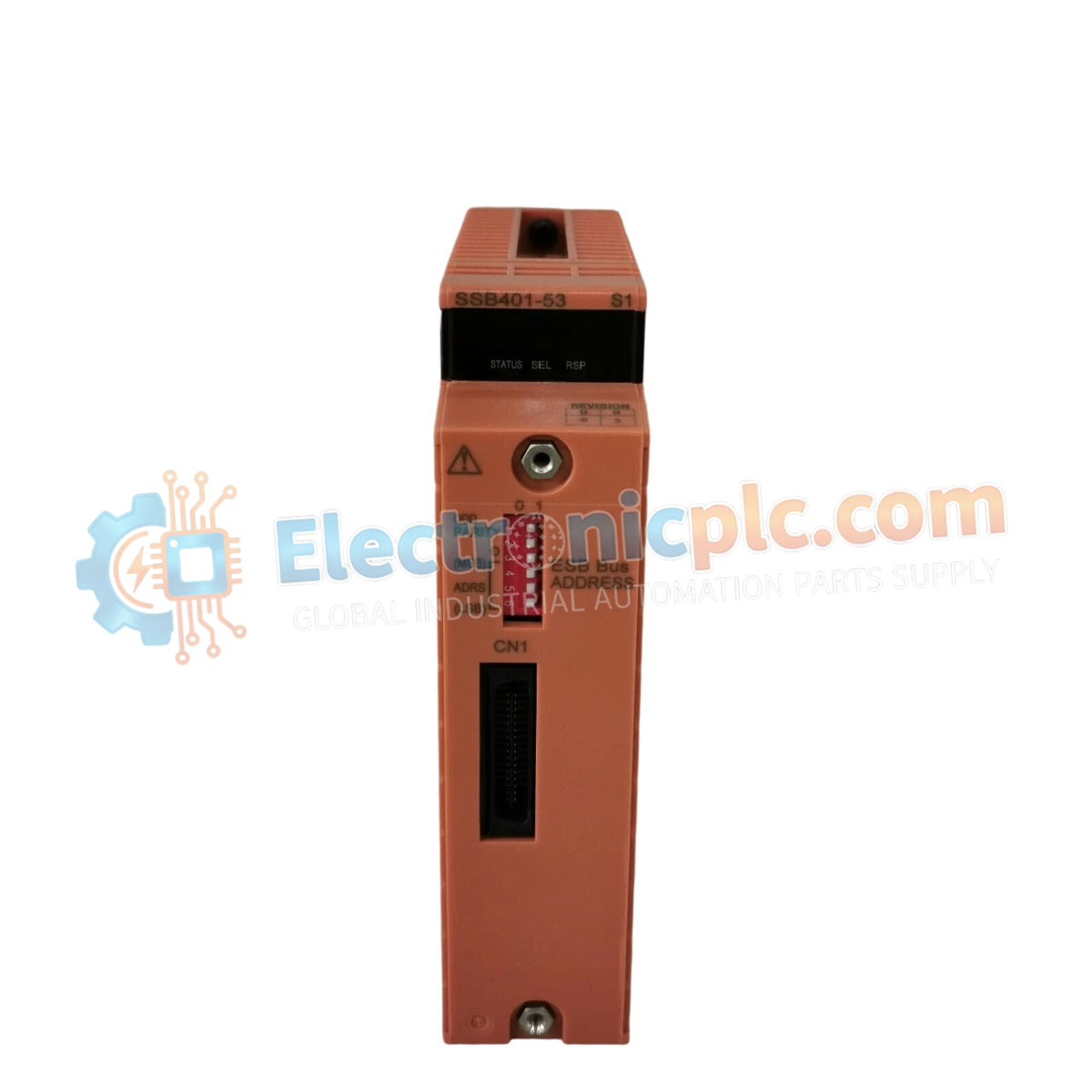
Configured for high-speed safety communication in ProSafe-RS SIS network platforms, the Yokogawa SSB401-53 (SSB401 ESB Bus Interface Slave Module) provides direct physical/electrical execution. This hardware component serves as the primary SSB401 slave module utilized to execute connectivity between safety node units (SNB10D) and the ESB bus across safety-critical control platforms.
| Parameter | Specification |
|---|---|
| Model | SSB401-53 S1 |
| Brand | Yokogawa |
| Origin | Japan |
| Weight | 0.5kg |
| Dimensions | Standard I/O module footprint |
| Operating Temp | -20 to 70 deg C |
| Power Consumption | 10 W |
| Communication Speed | 1 Mbps |
| Max Bus Length | 1,000 meters |
The SSB401-53 facilitates fail-safe state execution through the maintenance of high-speed, redundant communication paths across the ESB bus. The module is engineered for strict compliance with IEC 61508 safety standards, ensuring that communication between the safety controller and the SNB10D safety node units remains deterministic. The module architecture supports galvanic isolation to protect the safety bus from transient electrical faults and provides the necessary data integrity checks required for SIL-rated safety instrumentation systems.
Q: Does the SSB401-53 support hot-swapping while the safety system is active?
A: Yes, this module supports hot-swapping for maintenance. Ensure the local safety processor has acknowledged the module removal to prevent a false trip condition, and always verify system diagnostic status after insertion.
Q: Can the 1,000-meter ESB bus limit be exceeded using signal repeaters?
A: No. The 1,000-meter limit is defined by the propagation delay and signal integrity requirements of the ESB bus protocol. Exceeding this length compromises the deterministic timing required for IEC 61508 compliance.


