سلة التسوق الخاصة بي
0 عنصرًا
قطع غيار أصلية للأتمتة | توصيل سريع عالمي | ضمان لمدة 12 شهرًا — [احصل على عرض سعر]

Configured for precise process monitoring and alarm management in industrial instrumentation networks, the Yokogawa UT35A (UT35A Digital Indicator with Alarms) provides direct physical signal processing for primary variables and auxiliary...
التوافر: الكمية المتبقية: 99
توصيل موثوق به في جميع أنحاء العالم
ضمان استرداد الأموال خلال 30 يومًا
هل تحتاج إلى مزيد من التفاصيل؟ اقرأ سياسة الشحن وسياسة الاسترداد الكاملة.


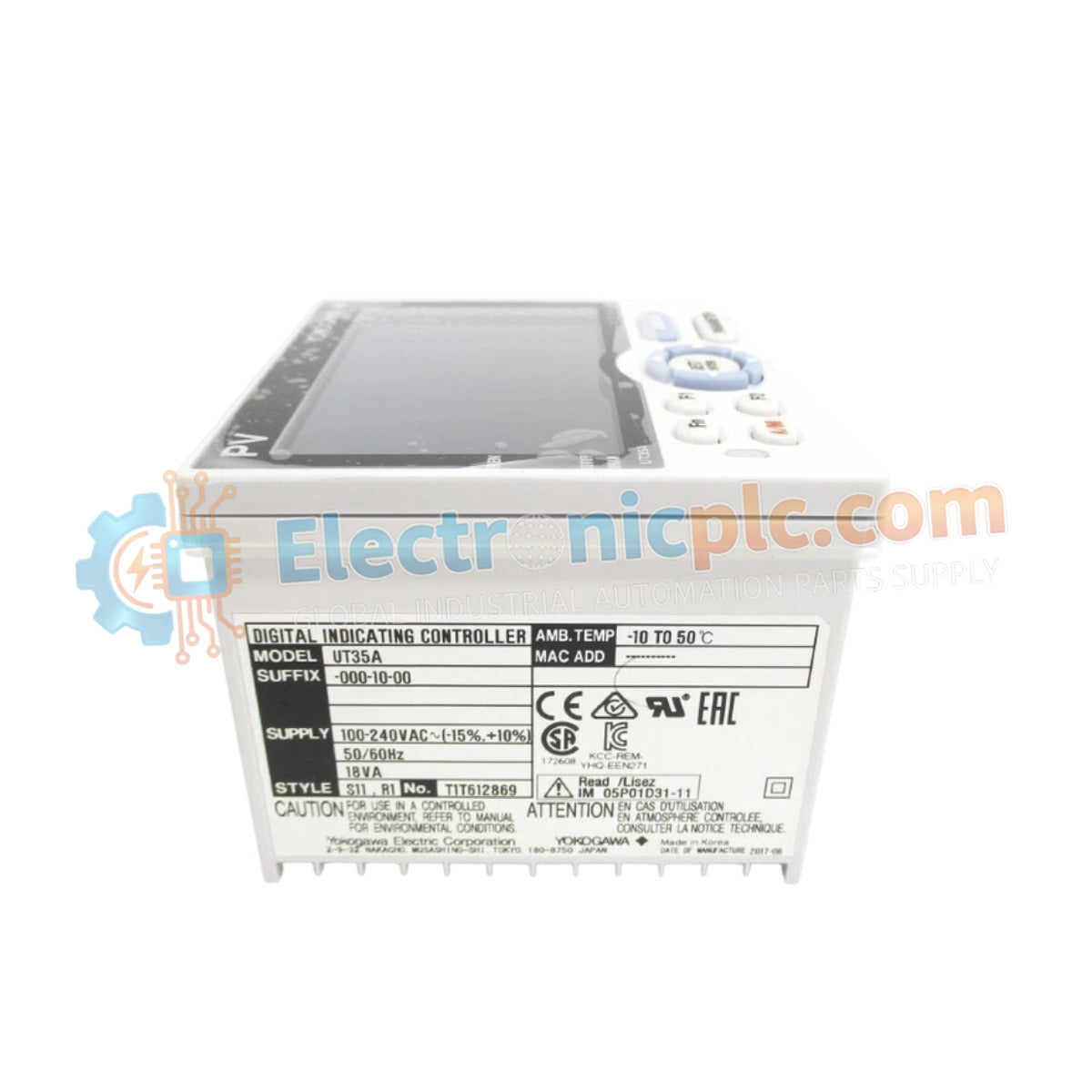
Configured for precise process monitoring and alarm management in industrial instrumentation networks, the Yokogawa UT35A (UT35A Digital Indicator with Alarms) provides direct physical signal processing for primary variables and auxiliary analog inputs.
| Parameter | Specification |
|---|---|
| Model | UT35A |
| Brand | Yokogawa |
| Origin | Japan |
| Weight | 0.50 kg |
| Dimensions | 9.6 cm x 9.6 cm x 6.5 cm |
| Operating Temp | -10 deg C to 50 deg C |
| Power Consumption | 18 VA |
| Power Supply | 100-240 VAC or 24 VAC/DC |
| PV Input | 1 (Isolated) |
| Aux. Analog Input | 1 (Non-isolated) |
| Control Output | Relay/Current/Voltage pulse |
The UT35A features an integrated 24 VDC loop power supply (LP option) to excite field-mounted transmitters, eliminating the requirement for external power distribution blocks. The input stage supports high-resolution signal conversion for primary process variables, while the non-isolated auxiliary input handles secondary data points. The unit provides configurable control outputs, including relay contacts rated for 250 VAC, 3 A, or current outputs ranging from 4-20 mA to 0-20 mA.
Q: Is the auxiliary analog input isolated from the primary PV input?
A: No, the auxiliary analog input on the UT35A is non-isolated. Care must be taken during wiring to ensure that the common-mode voltage between the auxiliary signal and the primary input does not exceed the specified isolation limits of the module to prevent measurement errors or damage.
Q: Can the UT35A be configured for heating/cooling control?
A: While the unit supports various control output types, heating/cooling functionality is typically restricted to specific model variations (such as the UT52A or UT32A series). Refer to the specific control output configuration of your unit to confirm dual-output capability.


