سلة التسوق الخاصة بي
0 عنصرًا
قطع غيار أصلية للأتمتة | توصيل سريع عالمي | ضمان لمدة 12 شهرًا — [احصل على عرض سعر]

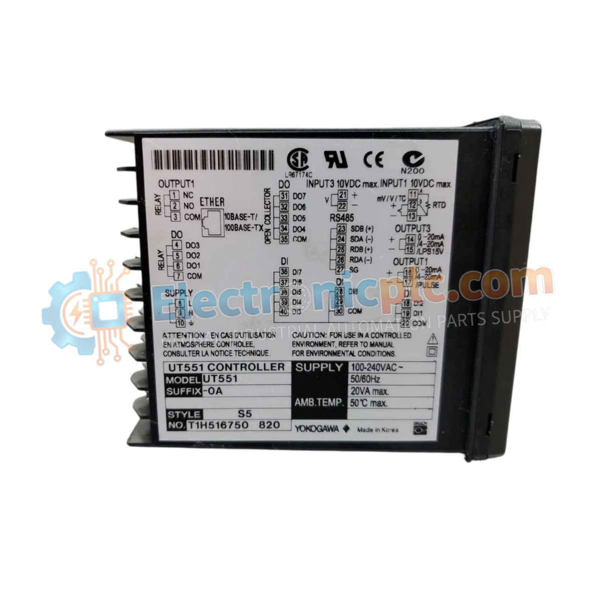
Configured for precise temperature and process loop regulation in industrial monitoring networks, the Yokogawa UT551 (UT551 Digital Indicating Controller) provides direct physical execution of PID control algorithms and alarm logic.
...التوافر: الكمية المتبقية: 99
توصيل موثوق به في جميع أنحاء العالم
ضمان استرداد الأموال خلال 30 يومًا
هل تحتاج إلى مزيد من التفاصيل؟ اقرأ سياسة الشحن وسياسة الاسترداد الكاملة.


Configured for precise temperature and process loop regulation in industrial monitoring networks, the Yokogawa UT551 (UT551 Digital Indicating Controller) provides direct physical execution of PID control algorithms and alarm logic.
| Parameter | Specification |
|---|---|
| Model | UT551 |
| Brand | Yokogawa |
| Origin | Japan |
| Weight | 1.00 lbs |
| Dimensions | 96 x 96 mm front panel |
| Operating Temp | -10 deg C to +50 deg C |
| Power Consumption | 100-240 VAC or 24 VDC |
| Protection Rating | IP66 |
| Input Types | Thermocouple, RTD, DC voltage, DC current |
| Control Outputs | Relay, Voltage pulse, Current, SSR drive |
| Communication | RS-485 Modbus RTU |
The UT551 integrates channel-to-channel isolation to maintain signal integrity across diverse input sensor types, including thermocouples and RTDs. The implementation of Super2 anti-hunting control algorithms facilitates stabilized process variable tracking, effectively reducing oscillation in high-gain control loops. The unit provides standard 4-20 mA HART loop protocol compatibility via external transducers where required, ensuring integration into broader DCS architectures. Cold junction compensation (CJC) is performed internally to ensure high-precision temperature measurements in variable ambient conditions.
Q: Can the RS-485 interface support multidrop configurations for integrated data acquisition?
A: Yes, the onboard RS-485 communication port supports Modbus RTU protocol, allowing the controller to function as a slave device in a multidrop network architecture for centralized monitoring.
Q: Does the controller maintain control loop integrity during firmware configuration changes?
A: The controller is designed to hold the last valid output state or a predefined fail-safe state during configuration updates; however, loop control is suspended while the device is in the parameter setup mode.


