سلة التسوق الخاصة بي
0 عنصرًا
قطع غيار أصلية للأتمتة | توصيل سريع عالمي | ضمان لمدة 12 شهرًا — [احصل على عرض سعر]

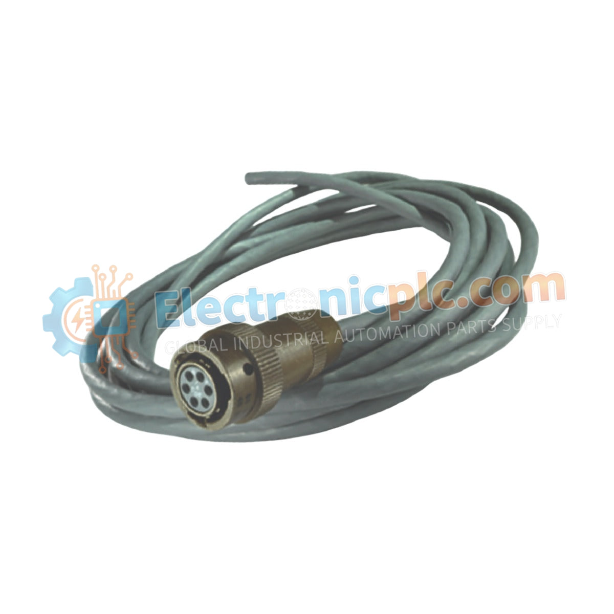
Configured for signal distribution in SENG control network architectures, the YOKOGAWA YCB146 (YCB146 T-shaped Control Bus Connector) provides direct physical execution of bus branching and signal propagation.
التوافر: في الأوراق المالية
توصيل موثوق به في جميع أنحاء العالم
ضمان استرداد الأموال خلال 30 يومًا
هل تحتاج إلى مزيد من التفاصيل؟ اقرأ سياسة الشحن وسياسة الاسترداد الكاملة.


Configured for signal distribution in SENG control network architectures, the YOKOGAWA YCB146 (YCB146 T-shaped Control Bus Connector) provides direct physical execution of bus branching and signal propagation.
The YCB146 is a fixed-design T-shaped connector component. No configurable suffixes or variants exist for this specific model number; the hardware is standardized for 10BASE-2 coaxial bus topology within the SENG framework.
| Parameter | Specification |
|---|---|
| Model | YCB146 |
| Brand | YOKOGAWA |
| Origin | Japan |
| Weight | 2 kg |
| Dimensions | Standard T-junction housing |
| Operating Temp | -20 deg C to 70 deg C |
| Power Consumption | Passive (0 W) |
| Connector Type | BNC (Male to Female/Female) |
| Interface Compatibility | 10BASE-2 Coaxial Bus |
The YCB146 serves as a physical junction node, facilitating the extraction of control signals from the primary backbone to local drop segments. In Yokogawa control network environments, the T-connector maintains the characteristic impedance of the transmission line to prevent signal reflections. Maintaining low contact resistance at the BNC interface is required to preserve the signal-to-noise ratio within the 10 Mbps data stream, ensuring consistent communication latency across all interconnected SENG nodes.
Q: Does the installation of the YCB146 T-connector introduce signal attenuation?
A: Yes. Every connection point in a 10BASE-2 network introduces a minor insertion loss. Excessive use of T-connectors on a single cable segment beyond the specified design limits of the SENG network may lead to signal degradation and packet transmission errors.
Q: Is this connector shielded against electromagnetic interference?
A: The housing is constructed to maintain the continuity of the coaxial shield. Proper seating of the BNC connectors ensures that the outer shell remains at ground potential, protecting the central signal conductor from external electrical noise.


