
سلة التسوق الخاصة بي
0 عنصرًا
قطع غيار أصلية للأتمتة | توصيل سريع عالمي | ضمان لمدة 12 شهرًا — [احصل على عرض سعر]

تعمل لوحةYOKOGAWA YPH105E (YT204001-FC PC BOARD) كمكون أجهزة داخلي بالغ الأهمية مصمم لتوجيه الإشارات وتنفيذ المنطق وإدارة الواجهة على مستوى النظام ضمن أجهزة Yokogawa الصناعية. تم تصميم لوحة الدوائر المطبوعة...
التوافر: في الأوراق المالية
توصيل موثوق به في جميع أنحاء العالم
ضمان استرداد الأموال خلال 30 يومًا
هل تحتاج إلى مزيد من التفاصيل؟ اقرأ سياسة الشحن وسياسة الاسترداد الكاملة.


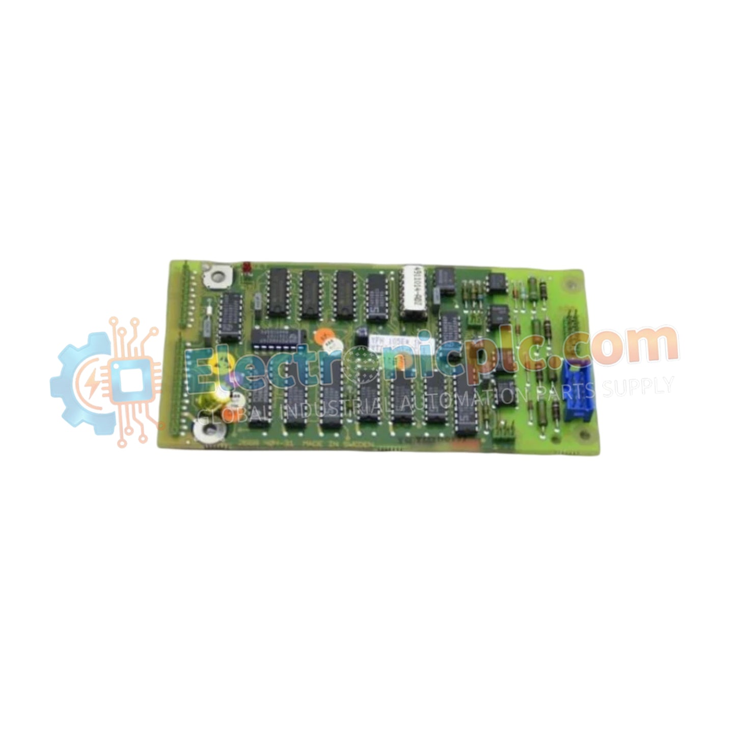
تعمل لوحةYOKOGAWA YPH105E (YT204001-FC PC BOARD) كمكون أجهزة داخلي بالغ الأهمية مصمم لتوجيه الإشارات وتنفيذ المنطق وإدارة الواجهة على مستوى النظام ضمن أجهزة Yokogawa الصناعية. تم تصميم لوحة الدوائر المطبوعة هذه لتسهيل التوصيل الإلكتروني الدقيق المطلوب بين مستشعرات الأجهزة الميدانية ووحدات معالجة التحكم الأساسية.
| المعلمة | المواصفات |
| النموذج | YPH105E |
| العلامة التجارية | YOKOGAWA |
| المنشأ | اليابان |
| الوزن | 0.3 كجم |
| الأبعاد | 7.6 سم × 5.1 سم × 12.7 سم |
| درجة حرارة التشغيل | المعيار الصناعي |
| نوع المكون | تجميع لوحة الكمبيوتر |
بصفتها مكونًا أساسيًا لهيكل الجهاز، تدعم YPH105E نقل الإشارات عالي السرعة وسلامة البيانات. تم تحسين تصميم الدائرة للحفاظ على مقاومة منخفضة ورفض ضوضاء الوضع المشترك عالية، مما يضمن عدم تلف الإشارات التناظرية أو الرقمية الحساسة من الميدان أثناء مراحل المعالجة. من خلال العمل كجسر منطق المعالجة المركزي، تضمن اللوحة أن وحدة التحكم يمكنها ترجمة المدخلات الميدانية إلى منطق تحكم قابل للتنفيذ بأقل قدر من التأخير.
س: هل هذه اللوحة متوافقة مع نماذج أجهزة Yokogawa المختلفة؟
ج: YPH105E خاصة بالنموذج. تعتمد التوافق على المراجعة الدقيقة لمضيف الجهاز. يجب عليك التحقق من رقم الجزء (YT204001-FC) مقابل اللوحة الموجودة في جهازك لضمان المطابقة الكهربائية والميكانيكية الدقيقة.
س: ما هي الاحتياطات التي يجب اتخاذها أثناء الصيانة أو الاستبدال؟
ج: نظرًا لأن هذه اللوحة تحتوي على دوائر متكاملة حساسة، يجب عليك اتباع بروتوكولات التفريغ الكهروستاتيكي (ESD) بدقة. استخدم سوارًا أرضيًا للحماية من التفريغ الكهروستاتيكي واحتفظ باللوحة في كيس مضاد للكهرباء الساكنة حتى لحظة التثبيت. لا تلمس أبدًا الموصلات المطلية بالذهب بأصابع عارية، حيث يمكن أن تسبب زيوت الجلد تآكلًا بمرور الوقت.
عزل الطاقة: قم دائمًا بعزل مصدر الطاقة عن رف الأجهزة قبل محاولة الوصول إلى الوحدات الداخلية أو إزالتها لمنع حدوث دوائر قصيرة عرضية.
المحاذاة: تأكد من محاذاة اللوحة تمامًا مع أدلة اللوحة الخلفية قبل الإدخال. لا تجبر اللوحة؛ يجب أن تنزلق بسلاسة في الموصل.
التثبيت: اضغط على اللوحة بقوة حتى يتم تثبيت موصل الحافة بالكامل. يمكن أن يؤدي التثبيت غير الصحيح إلى أعطال إشارة متقطعة أو عدم استقرار النظام.
التحقق: بعد التثبيت، قم بإجراء اختبار ذاتي عند التشغيل (POST) عبر واجهة تشخيص الجهاز للتأكد من تهيئة اللوحة بشكل صحيح وعدم وجود أخطاء في حالة الأجهزة.
التثبيت: قم بتأمين اللوحة باستخدام أي براغي تثبيت ذات صلة لضمان بقائها مقاومة للاهتزاز في البيئات الصناعية الشاقة.


