
Carrito
0 artículos
¿Tienes una cuenta?
Inicia sesión para finalizar tus compras con mayor rapidez.
Repuestos originales de automatización | Envío exprés a todo el mundo | Garantía de 12 meses — [Solicite presupuesto]

Configurado para la gestión precisa de la temperatura y el lazo de proceso, el YOKOGAWA UT55A-040-11 (Controlador Indicador Digital UT55A-040-11-00/LP) proporciona procesamiento directo de señales y control de puntos de...
Disponibilidad: En existencias
Entrega confiable a nivel mundial
Garantía de devolución de dinero de 30 días
¿Necesitas más información? Consulta nuestra Política de envíos y reembolsos completa.


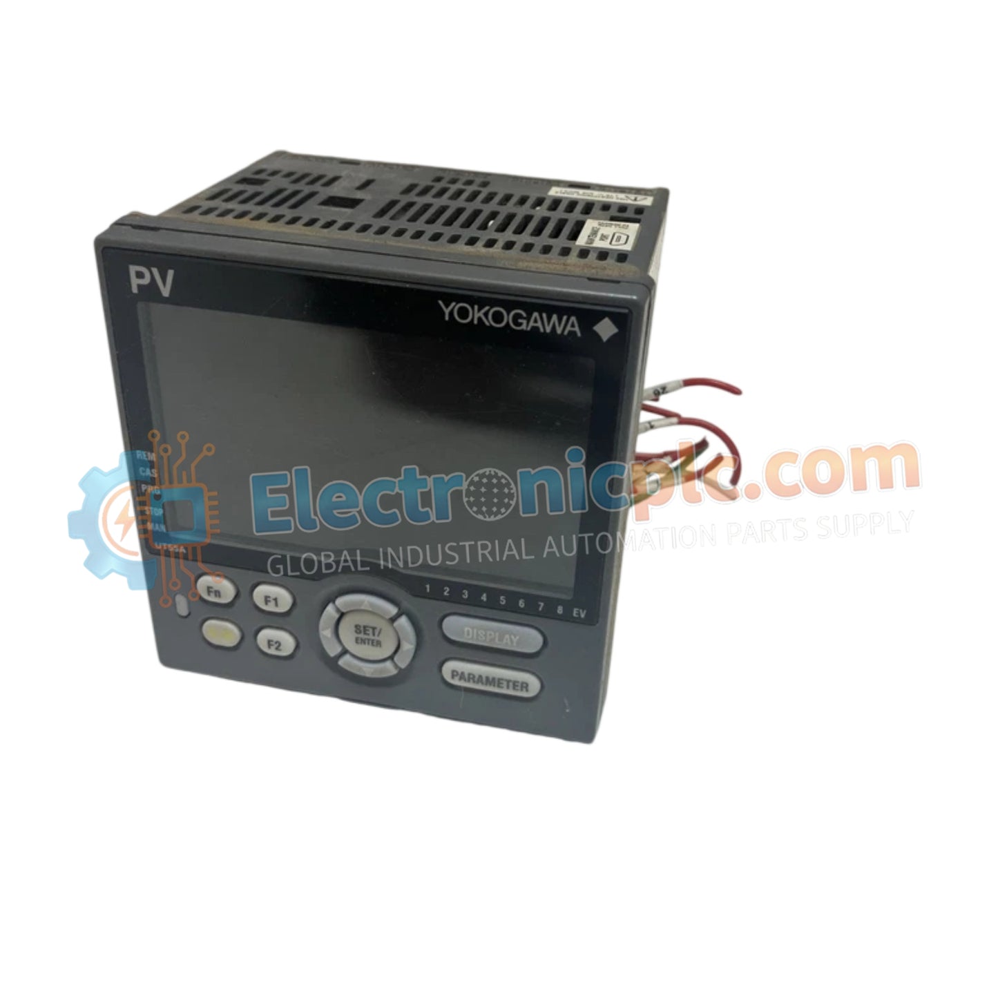
Configurado para la gestión precisa de la temperatura y el lazo de proceso, el YOKOGAWA UT55A-040-11 (Controlador Indicador Digital UT55A-040-11-00/LP) proporciona procesamiento directo de señales y control de puntos de ajuste a través de redes de instrumentación distribuidas.
| Parámetro | Especificación |
|---|---|
| Modelo | UT55A-040-11-00/LP |
| Marca | YOKOGAWA |
| Origen | Japón |
| Peso | 1.12kg |
| Dimensiones | Factor de forma estándar 1/4 DIN |
| Temperatura de funcionamiento | No especificado |
| Consumo de energía | 18 VA |
| Tensión de alimentación | 100-240 VCA, 50/60 Hz |
| Pantalla | LCD de 5 dígitos |
| Configuración de entrada | Entrada analógica auxiliar remota + 1 entrada digital |
El controlador se integra sin problemas en entornos de proceso estándar utilizando los protocolos de lazo HART de 4-20 mA para la comunicación de dispositivos de campo. Presenta aislamiento de canal a canal para garantizar que las entradas de termopares o RTD estén protegidas contra la interferencia de voltaje en modo común. El circuito interno proporciona una compensación avanzada de la unión fría (CJC) para mantener lecturas de alta precisión en condiciones de temperatura ambiente variables, asegurando una ejecución estable del punto de ajuste dentro de los lazos de instrumentación DCS.
P: ¿El UT55A admite la calibración en campo de las entradas analógicas?
R: Sí, la unidad permite offsets de calibración basados en software para corregir la resistencia de los cables del sensor o las imprecisiones de los termopares, siempre que el controlador esté en el modo de configuración adecuado.
P: ¿Se puede integrar este modelo en una red Profibus o Fieldbus existente?
R: El modelo base listado utiliza E/S analógicas/digitales estándar; la integración en redes de bus de campo digitales generalmente requiere un módulo de comunicación variante específico o una interfaz de pasarela.


