Carrito
0 artículos
¿Tienes una cuenta?
Inicia sesión para finalizar tus compras con mayor rapidez.
Repuestos originales de automatización | Envío exprés a todo el mundo | Garantía de 12 meses — [Solicite presupuesto]

Configured for data transmission synchronization in CENTUM VP control systems, the YOKOGAWA EC402-50 (EC402-50 ESB Bus Coupler Module) provides direct physical and electrical execution of ESB bus signal coupling between...
Disponibilidad: Bajas existencias: quedan 99
Entrega confiable a nivel mundial
Garantía de devolución de dinero de 30 días
¿Necesitas más información? Consulta nuestra Política de envíos y reembolsos completa.

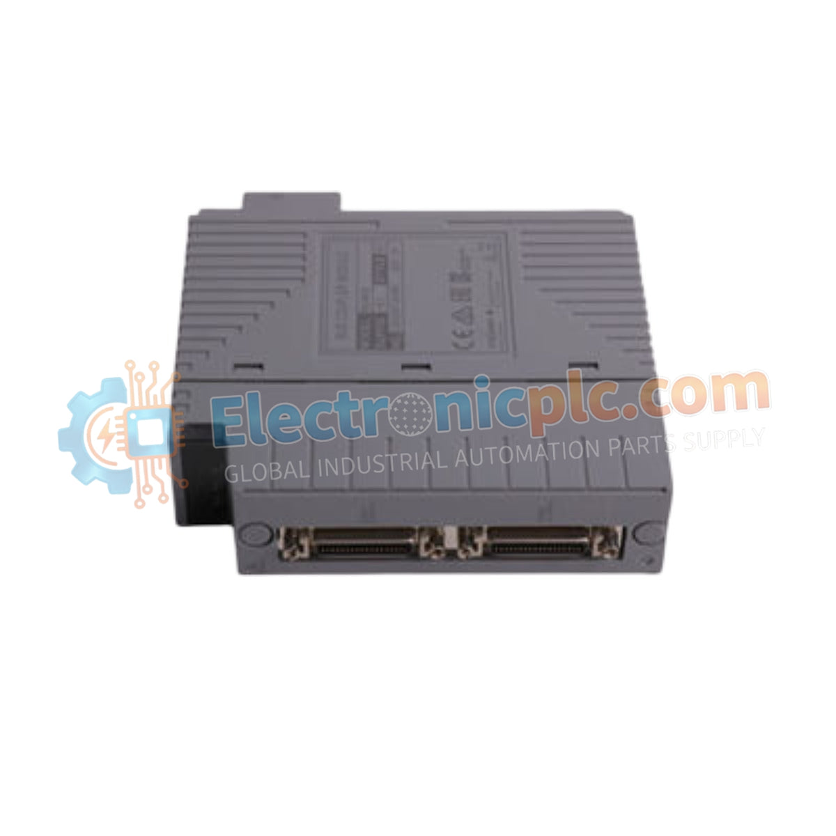
Configured for data transmission synchronization in CENTUM VP control systems, the YOKOGAWA EC402-50 (EC402-50 ESB Bus Coupler Module) provides direct physical and electrical execution of ESB bus signal coupling between the control station and remote I/O nodes.
| Parameter | Specification |
|---|---|
| Model | EC402-50 |
| Brand | YOKOGAWA |
| Origin | Japan |
| Weight | 0.12 kg |
| Dimensions | 10.2 x 8 x 5 cm |
| Operating Temp | Standard industrial range |
| Power Consumption | Subject to backplane supply |
| Bus Interface | ESB Bus |
| Mounting Type | Rack mount |
The EC402-50 module maintains signal integrity through high-speed ESB bus communication protocols. The internal architecture facilitates galvanic isolation to mitigate noise interference within the control loop. By managing the signal conversion and coupling functions, the module ensures consistent throughput for I/O data packets. Impedance matching across the ESB bus architecture is controlled to prevent reflection, ensuring that the 4-20 mA HART loop protocol signals remain stable across the distributed control network. Proper termination of the bus remains a requirement for minimizing signal distortion during high-velocity data transfer between the bus interface and the field instruments.
Q: Can the EC402-50 module be replaced while the system is powered?
A: No, this module does not support hot-swap operations. The control station power must be de-energized before removing or installing the module to prevent electrical damage to the backplane pins.
Q: What is the primary function of the ESB bus coupling in this configuration?
A: The module acts as an interface that manages communication signals between the field control station (FCS) and the I/O nodes, ensuring deterministic timing and data consistency across the bus.

