
Carrito
0 artículos
¿Tienes una cuenta?
Inicia sesión para finalizar tus compras con mayor rapidez.
Repuestos originales de automatización | Envío exprés a todo el mundo | Garantía de 12 meses — [Solicite presupuesto]

Configurada para la conmutación de señales digitales de alta densidad en sistemas CENTUM VP, la Yokogawa ARM55C-000 (Placa de Salida de Relé Mecánico ARM55C) proporciona una ejecución física y eléctrica...
Disponibilidad: En existencias
Entrega confiable a nivel mundial
Garantía de devolución de dinero de 30 días
¿Necesitas más información? Consulta nuestra Política de envíos y reembolsos completa.


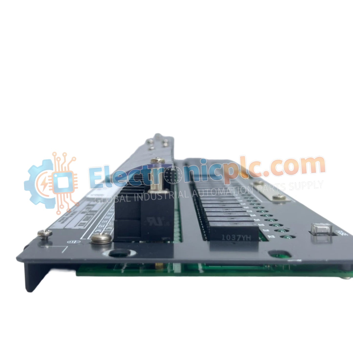
Configurada para la conmutación de señales digitales de alta densidad en sistemas CENTUM VP, la Yokogawa ARM55C-000 (Placa de Salida de Relé Mecánico ARM55C) proporciona una ejecución física y eléctrica directa de la conmutación de salida de contacto seco para dispositivos de campo.
| Parámetro | Especificación |
|---|---|
| Modelo | ARM55C-000 |
| Marca | Yokogawa |
| Origen | Japón |
| Peso | 2.2 kg |
| Dimensiones | Estándar de montaje en rack de 19 pulgadas |
| Temperatura de funcionamiento | 0 °C a 50 °C |
| Consumo de energía | 24 V CC (0.85 A máximo) |
| Canales de salida | 32 relés de contacto seco (NA/NC) |
| Carga máxima | 250 V CA/30 V CC @ 2 A; 125 V CC @ 0.1 A |
| Carga mínima | 5 V CC @ 10 mA |
El ARM55C-000 utiliza relés mecánicos para proporcionar un aislamiento galvánico completo entre los circuitos lógicos de baja tensión del DCS y los circuitos de carga del lado de campo. Este aislamiento evita que los transitorios de alta tensión se propaguen de vuelta a la placa base del CENTUM VP. Cada canal es configurable en campo para operación Normalmente Abierto (NA) o Normalmente Cerrado (NC), lo que permite que la placa ejecute una lógica de estado a prueba de fallos basada en requisitos específicos de seguridad del proceso. La rigidez dieléctrica de 2 kV entre los terminales de campo y la carcasa garantiza una protección robusta contra fallas eléctricas industriales comunes.
P: ¿Se puede utilizar el ARM55C-000 para salidas de pulsos de alta velocidad?
R: No. Como placa de relé mecánico, la velocidad de conmutación está limitada por el tiempo de recorrido mecánico de los contactos del relé. Está diseñada para control digital de baja velocidad, como el accionamiento de válvulas solenoides o bobinas de contactores, y no es adecuada para modulación por ancho de pulso (PWM) de alta frecuencia o pulsaciones rápidas.
P: ¿Cuál es el requisito de carga mínima para evitar la oxidación de los contactos?
R: Para mantener un cierre de contacto fiable a lo largo del tiempo, cada canal requiere una carga mínima de 5 V CC a 10 mA. Operar por debajo de este umbral puede provocar la formación de capas de óxido aislantes en los contactos del relé, lo que resulta en un funcionamiento intermitente.


