
Carrito
0 artículos
¿Tienes una cuenta?
Inicia sesión para finalizar tus compras con mayor rapidez.
Repuestos originales de automatización | Envío exprés a todo el mundo | Garantía de 12 meses — [Solicite presupuesto]

El Yokogawa NFAR181-S00/R8S0, también catalogado como el módulo de entrada RTD NFAR181, funciona como un componente de hardware dedicado para la adquisición de señales de temperatura de 12 canales dentro...
Disponibilidad: En existencias
Entrega confiable a nivel mundial
Garantía de devolución de dinero de 30 días
¿Necesitas más información? Consulta nuestra Política de envíos y reembolsos completa.


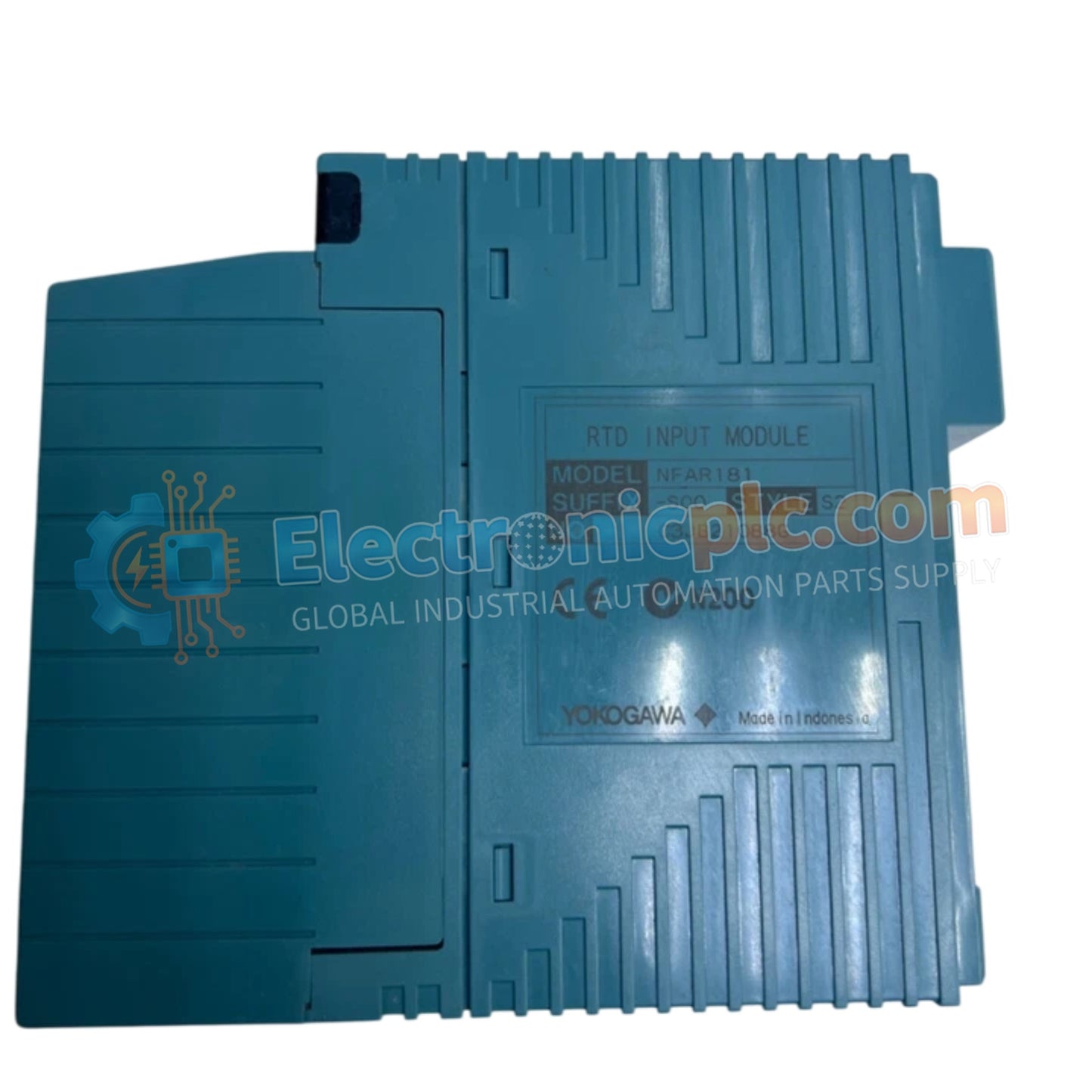
El Yokogawa NFAR181-S00/R8S0, también catalogado como el módulo de entrada RTD NFAR181, funciona como un componente de hardware dedicado para la adquisición de señales de temperatura de 12 canales dentro de plataformas de sistemas de control distribuido.
| Parámetro | Especificación |
|---|---|
| Modelo | NFAR181-S00/R8S0 |
| Marca | Yokogawa |
| Origen | Japón |
| Peso | 0,2 kg |
| Dimensiones | Formato de módulo N-IO estándar |
| Temperatura de funcionamiento | 0 a 50 grados C |
| Consumo de energía | 450 mA a 5 V CC |
| Canales de entrada | 12 (aislados) |
| Precisión | +/- 0,03 % del rango completo |
| Tensión de resistencia | 1500 V CA (1 min) |
El módulo NFAR181 proporciona detección de temperatura de alta densidad a través de 12 canales de entrada aislados galvánicamente. Esta arquitectura garantiza un aislamiento efectivo de canal a canal, evitando que el ruido de modo común y los bucles de tierra afecten la precisión de la medición en entornos de control distribuido. El módulo facilita el procesamiento preciso de la señal RTD con una deriva de temperatura mínima, limitada a 30 ppm/°C. Está optimizado para la integración con configuraciones RTD de 4, 3 o 2 hilos, siempre que la resistencia total por hilo no exceda los 40 ohmios.
P: ¿Es compatible el NFAR181-S00/R8S0 con el intercambio en caliente bajo tensión?
R: Sí, este módulo admite el intercambio en caliente dentro del entorno del sistema N-IO, lo que permite su reemplazo sin interrumpir la comunicación de otros módulos en el mismo nodo.
P: ¿Cuál es la importancia de la especificación de tensión de resistencia de 1500 V CA?
R: Esta clasificación define la barrera de aislamiento eléctrico entre los terminales de entrada de campo y la placa posterior interna del sistema, protegiendo los circuitos del controlador de transitorios o sobretensiones de alto voltaje originados en el lado del campo.


