
Carrito
0 artículos
¿Tienes una cuenta?
Inicia sesión para finalizar tus compras con mayor rapidez.
Repuestos originales de automatización | Envío exprés a todo el mundo | Garantía de 12 meses — [Solicite presupuesto]

Configurado para control discreto en sistemas de control autónomos STARDOM, el YOKOGAWA NFDR541-P00 S2 (módulo de salida de relé NFDR541) proporciona ejecución física/eléctrica directa. Este componente de hardware gestiona 16...
Disponibilidad: En existencias
Entrega confiable a nivel mundial
Garantía de devolución de dinero de 30 días
¿Necesitas más información? Consulta nuestra Política de envíos y reembolsos completa.


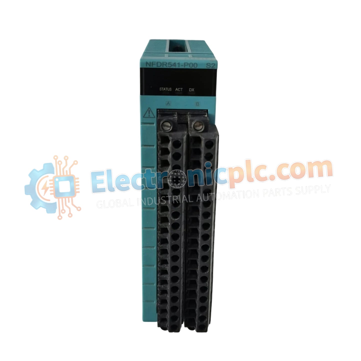
Configurado para control discreto en sistemas de control autónomos STARDOM, el YOKOGAWA NFDR541-P00 S2 (módulo de salida de relé NFDR541) proporciona ejecución física/eléctrica directa. Este componente de hardware gestiona 16 canales de contacto seco independientes, facilitando la conmutación de solenoides, relés intermedios e indicadores dentro de las plataformas de control FCN o FCJ.
| Parámetro | Especificación |
|---|---|
| Modelo | NFDR541-P00 S2 |
| Marca | YOKOGAWA |
| Origen | JAPÓN |
| Peso | 0,3 kg |
| Dimensiones | 3,3 cm x 12,7 cm x 12,7 cm |
| Temperatura de funcionamiento | -10 a 55 grados C |
| Consumo de energía | 780 mA (a 5 VCC) |
| Canales de salida | 16 |
| Tipo de salida | Relé (contacto seco) |
| Corriente máxima (CC/CA) | 5 A (CC) / 3 A (CA) |
El NFDR541-P00 S2 proporciona un robusto aislamiento eléctrico entre los circuitos de control internos y los contactos de salida del lado del campo. Con una tensión nominal de aislamiento de 2000 V CA, este módulo evita que los transitorios de alta tensión en el lado del campo se propaguen de nuevo al bus del controlador FCN/FCJ. La arquitectura de contacto seco permite una integración versátil en múltiples niveles de tensión, admitiendo cargas de CC de hasta 110 V y cargas de CA de hasta 240 V sin necesidad de etapas de conversión de señal externas.
P: ¿El NFDR541-P00 S2 admite el intercambio en caliente para el mantenimiento?
R: El intercambio en caliente es permisible siempre que la arquitectura del sistema y la configuración de la unidad base permitan el reemplazo del módulo en línea; sin embargo, la alimentación de campo debe aislarse de los contactos del relé antes de la extracción para garantizar la seguridad del operador y evitar el arco de contacto.
P: ¿Los 16 canales de salida son direccionables de forma independiente y están aislados entre sí?
R: Los canales son direccionables de forma independiente para la lógica de control; sin embargo, los usuarios deben verificar la agrupación de terminales comunes en el bloque de terminales para confirmar los límites de aislamiento entre bancos de canales específicos.


