
Carrito
0 artículos
¿Tienes una cuenta?
Inicia sesión para finalizar tus compras con mayor rapidez.
Repuestos originales de automatización | Envío exprés a todo el mundo | Garantía de 12 meses — [Solicite presupuesto]

Configured for relay output switching in autonomous control systems, the YOKOGAWA NFDR541 (NFDR541) Relay Output Module provides direct physical and electrical execution for STARDOM platform architectures.
Disponibilidad: Bajas existencias: quedan 50
Entrega confiable a nivel mundial
Garantía de devolución de dinero de 30 días
¿Necesitas más información? Consulta nuestra Política de envíos y reembolsos completa.


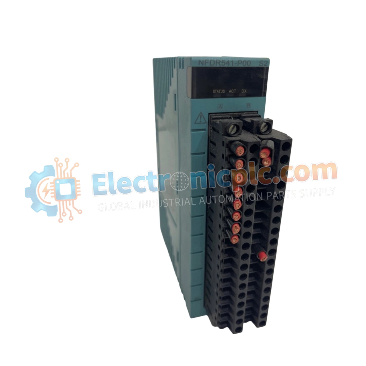
Configured for relay output switching in autonomous control systems, the YOKOGAWA NFDR541 (NFDR541) Relay Output Module provides direct physical and electrical execution for STARDOM platform architectures.
| Parameter | Specification |
|---|---|
| Model | NFDR541 |
| Brand | YOKOGAWA |
| Origin | Japan |
| Weight | 0.3 kg |
| Dimensions | 3.3 cm x 12.7 cm x 12.7 cm |
| Operating Temp | -10 deg C to +55 deg C |
| Power Consumption | 780 mA max at 5 VDC |
| Output Channels | 16 dry contact relay channels |
| Switching Ratings | DC: 24 to 110 V at 5 A max; AC: 100 to 240 V at 3 A max |
The module incorporates robust channel-to-channel and power-to-circuitry isolation rated at 2000 V AC to prevent ground loops and high-voltage transient feedback across multi-load industrial switching loops. Signal conditioning circuitry translates digital control states into reliable dry-contact closures for field solenoids, indicators, and actuators. Built-in diagnostic tracking continuously monitors relay coil states and backplane power bus stability, ensuring precise execution and fault reporting within FCN and FCJ controller networks.
Q: What is the maximum switching current capacity per channel for DC and AC loads?
A: The relay contacts support up to 5 A per channel for DC loads (24 to 110 V) and up to 3 A per channel for AC loads (100 to 240 V).
Q: Does the NFDR541 module support hot-insertion and removal under power?
A: Physical maintenance requires de-energization of external field power supplies connected to the relay terminals to prevent arcing and protect internal switching components.
Mount the NFDR541 module securely onto standard industrial DIN rails or direct panel enclosures, ensuring adequate clearance above and below the housing for thermal dissipation. Terminate field actuator wiring to the pressure clamp terminals using appropriately rated cables, keeping inductive load suppression diodes installed across DC loads. Verify terminal clamping security and confirm isolation voltage withstand limits prior to system energization.


