
Carrito
0 artículos
¿Tienes una cuenta?
Inicia sesión para finalizar tus compras con mayor rapidez.
Repuestos originales de automatización | Envío exprés a todo el mundo | Garantía de 12 meses — [Solicite presupuesto]

Configurado para la validación de diagnóstico en bucles de instrumentación de entrada digital, el YOKOGAWA SCB110-S0 (adaptador de comprobación de cableado SCB110-S0) proporciona monitorización y verificación física directa de circuitos...
Disponibilidad: En existencias
Entrega confiable a nivel mundial
Garantía de devolución de dinero de 30 días
¿Necesitas más información? Consulta nuestra Política de envíos y reembolsos completa.


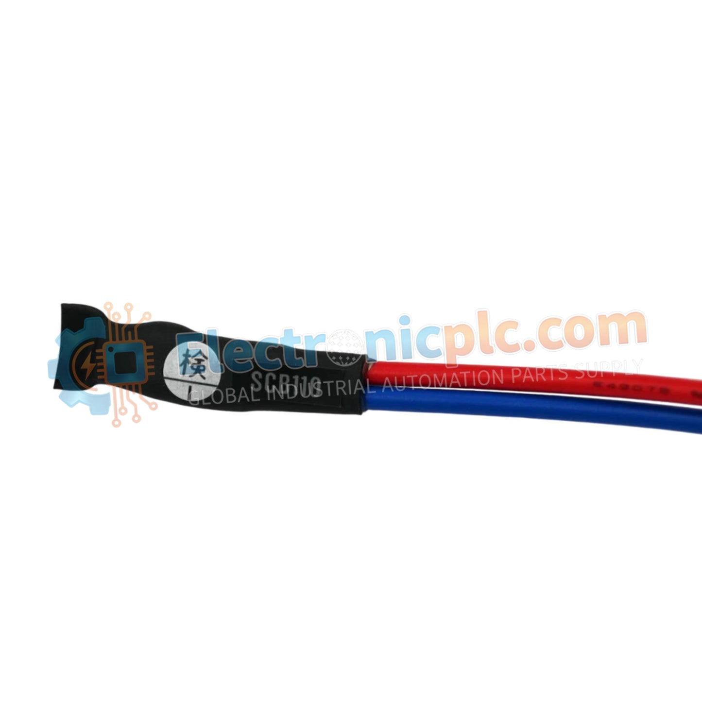
Configurado para la validación de diagnóstico en bucles de instrumentación de entrada digital, el YOKOGAWA SCB110-S0 (adaptador de comprobación de cableado SCB110-S0) proporciona monitorización y verificación física directa de circuitos de señal digital a través de plataformas PLC y DCS.
| Parámetro | Especificación |
|---|---|
| Modelo | SCB110-S0 |
| Marca | YOKOGAWA |
| Origen | Japón |
| Peso | 0,5 kg |
| Dimensiones | Factor de forma de interfaz de terminal estándar |
| Temperatura de funcionamiento | No especificado |
| Consumo de energía | Pasivo (alimentado por bucle) |
| Tipo de entrada | Verificación de entrada digital (DI) |
| Montaje | Interfaz de bloque de terminales |
| Protección | Carcasa industrial estándar |
El SCB110-S0 está diseñado para facilitar la verificación rápida del cableado de campo sin requerir señales en vivo de los transmisores de campo. Al actuar como un puente de diagnóstico, el adaptador permite a los técnicos simular estados de entrada, asegurando que el aislamiento de canal a canal y la integridad de la ruta de la señal se confirmen antes de la puesta en marcha completa del sistema. Esta capacidad de verificación física es esencial para identificar fallas de cableado, como circuitos abiertos o condiciones de cortocircuito a tierra, dentro de arquitecturas complejas de E/S digitales.
P: ¿El SCB110-S0 requiere alimentación externa para la verificación del cableado?
R: No, el adaptador es un dispositivo pasivo diseñado para interactuar con la fuente de alimentación del módulo de E/S existente. Utiliza la corriente del bucle para facilitar la verificación del estado durante la fase de prueba.
P: ¿Se puede dejar este adaptador en el circuito durante el funcionamiento normal?
R: El SCB110-S0 está destinado a fines de diagnóstico y puesta en marcha. Debe retirarse de la ruta de la señal una vez que se complete la verificación del cableado para garantizar que el módulo de E/S funcione dentro de sus parámetros de diseño.


