
Carrito
0 artículos
¿Tienes una cuenta?
Inicia sesión para finalizar tus compras con mayor rapidez.
Repuestos originales de automatización | Envío exprés a todo el mundo | Garantía de 12 meses — [Solicite presupuesto]

Configurado para una monitorización de procesos de precisión y la gestión de señales de alarma, el YOKOGAWA UM33A-000-11 (Indicador Digital UM33A-000-11/LP) proporciona procesamiento directo de señales físicas para bucles de...
Disponibilidad: En existencias
Entrega confiable a nivel mundial
Garantía de devolución de dinero de 30 días
¿Necesitas más información? Consulta nuestra Política de envíos y reembolsos completa.


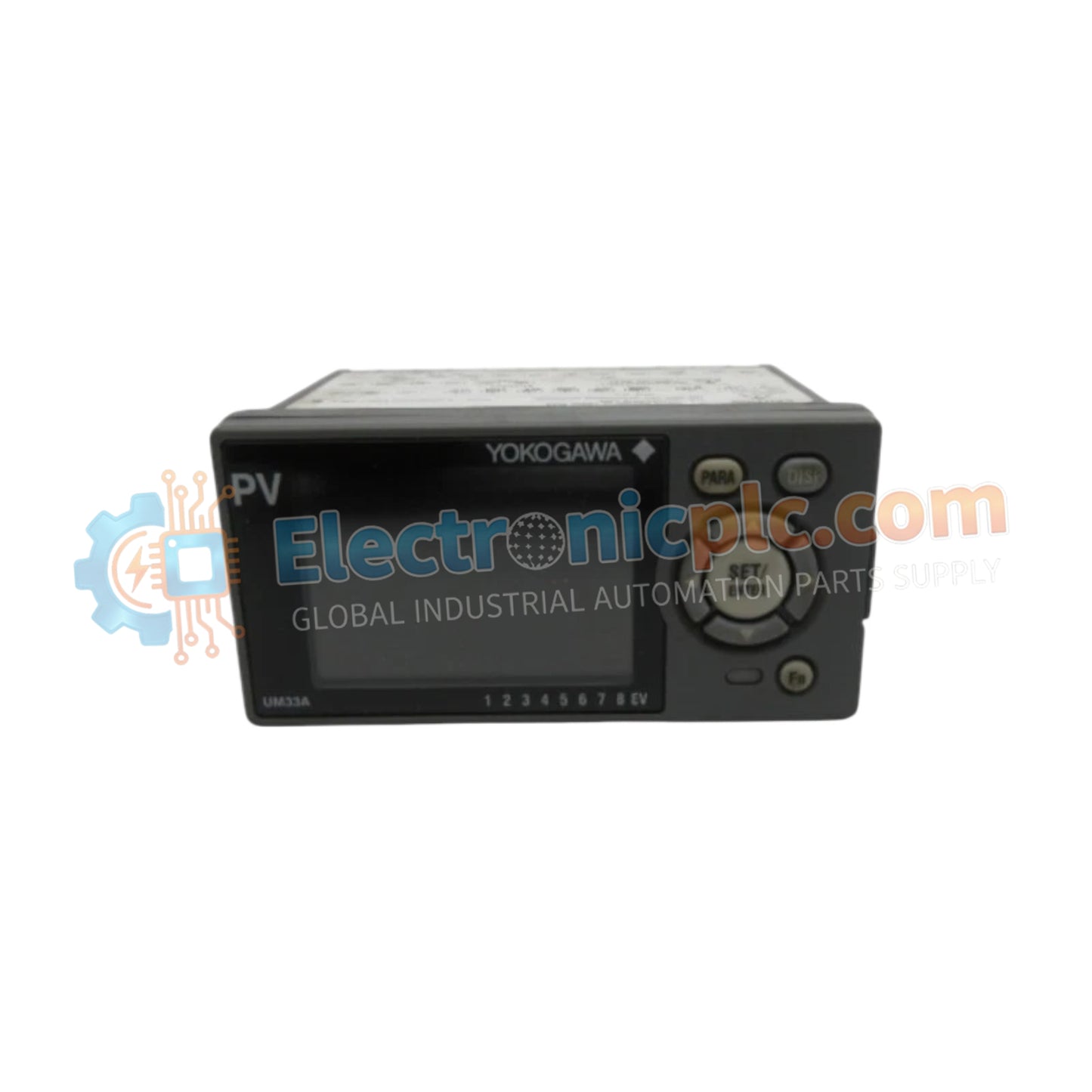
Configurado para una monitorización de procesos de precisión y la gestión de señales de alarma, el YOKOGAWA UM33A-000-11 (Indicador Digital UM33A-000-11/LP) proporciona procesamiento directo de señales físicas para bucles de instrumentación industrial.
| Parámetro | Especificación |
|---|---|
| Modelo | UM33A-000-11/LP |
| Marca | YOKOGAWA |
| Origen | Japón |
| Peso | 0,5 kg |
| Dimensiones | 9,6 cm x 4,8 cm x 6,5 cm |
| Corte de panel | 9,2 cm x 4,5 cm |
| Temperatura de funcionamiento | No especificado |
| Consumo de energía | No especificado |
| Tipo de entrada | Contacto sin tensión de 2 puntos o transistor |
| Tipo de salida | Retransmisión de 4-20 mA DC o 0-20 mA DC |
| Configuración de alarma | 3 puntos (contacto 1a) + 1 punto (contacto 1c) |
| Montaje | Hasta 30 grados por encima de la horizontal |
El UM33A utiliza principios de protocolo de bucle HART estándar de 4-20 mA para la retransmisión, lo que permite el envío de datos sin problemas a nodos de monitorización DCS o PLC secundarios. El dispositivo proporciona aislamiento galvánico interno entre la entrada de señal y la salida de retransmisión para evitar bucles de tierra. Presenta capacidades específicas de ejecución de lógica de alarma, lo que garantiza que las desviaciones del proceso se detecten y se señalicen de inmediato a través de la arquitectura de contacto de relé independiente 1a/1c.
P: ¿Se puede montar el UM33A en una orientación vertical o inclinada hacia abajo?
R: No, el montaje está restringido a un máximo de 30 grados por encima de la horizontal. La inclinación hacia abajo está estrictamente prohibida para mantener una disipación de calor adecuada y la longevidad de los componentes internos.
P: ¿Cómo se utiliza la fuente de alimentación de bucle de 24 VDC?
R: La opción /LP proporciona alimentación dedicada a los transmisores de campo directamente a través del bucle de señal, eliminando la necesidad de fuentes de alimentación externas para bucles estándar de 4-20 mA.


