Carrito
0 artículos
¿Tienes una cuenta?
Inicia sesión para finalizar tus compras con mayor rapidez.
Repuestos originales de automatización | Envío exprés a todo el mundo | Garantía de 12 meses — [Solicite presupuesto]

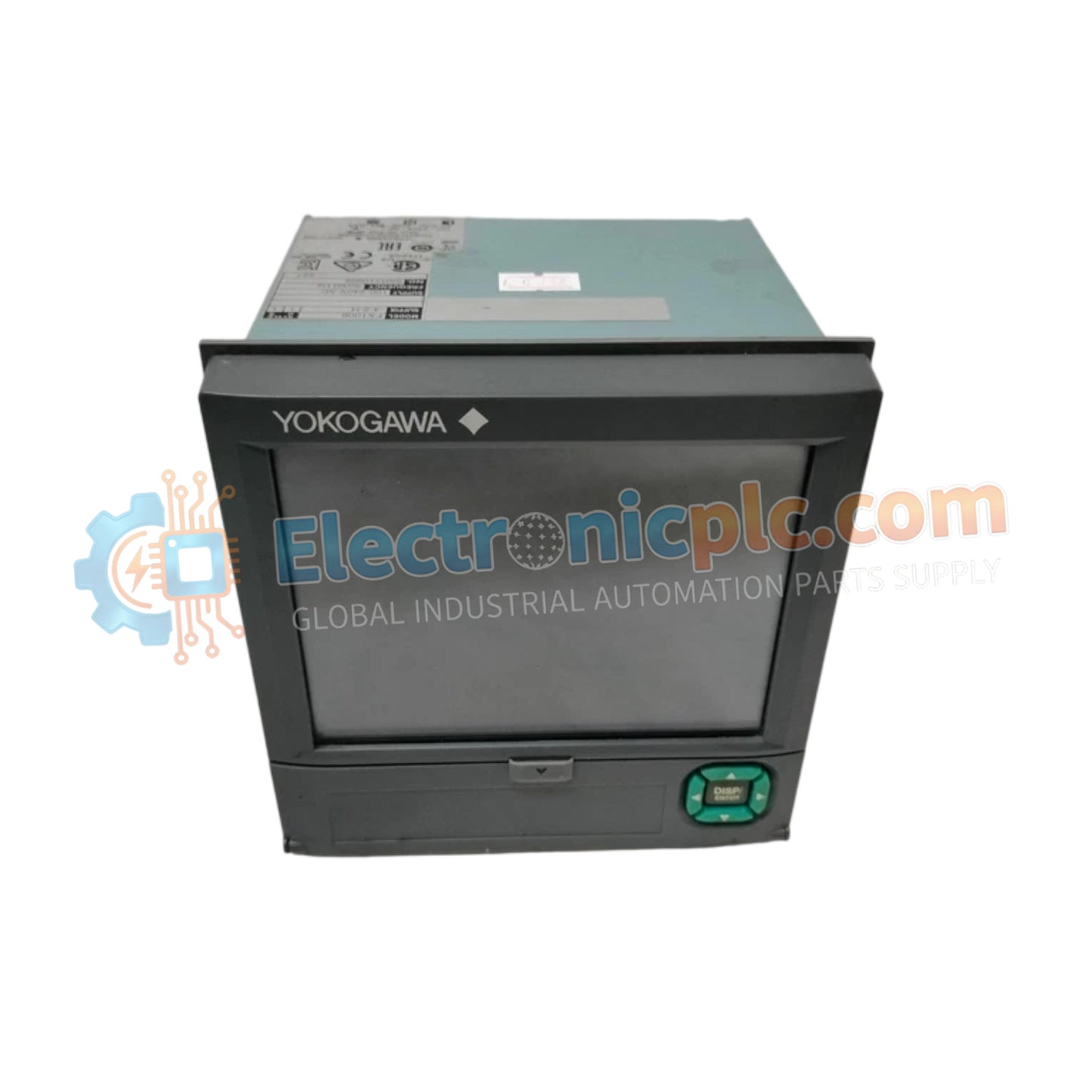
The Yokogawa UP55A-001-11-00/AP serves as the primary UP55A-001-11-00/AP Program Controller utilized to execute multi-pattern thermal profiling and loop regulation across distributed control system platforms.
| Parameter | Specification |
|---|---|
| Model | UP55A-001-11-00/AP |
| Brand | Yokogawa |
| Origin | Standard Industrial Specification |
| Weight | 8.0 kg |
| Dimensions | 6.5 cm x 9.6 cm x 9.6 cm |
| Operating Temp | Standard Industrial Rating |
| Power Consumption | Standard Line Power |
| Program Patterns | Max 99 with /AP option |
| Segment Time | 0.00 to 999.59 hour.minute or minute.second |
| Display Type | 5-digit 14-segment active color LCD |
The hardware configuration maintains strict electrical isolation across input and control output channels to suppress common-mode electrical noise and prevent ground fault propagation between field loops. Integration with standard 4-20 mA HART loop protocol parameters and process instrumentation interfaces ensures transparent transmission of analog and digital data streams directly to control system monitoring units without signal degradation.
Q: What are the restrictions regarding memory retention during power interruptions on the UP55A-001-11-00/AP controller?
A: Program profiles and configuration parameters are stored in non-volatile flash memory, preserving user-defined setpoints and pattern structures across unexpected power-loss events.
Q: How does the controller handle synchronized program execution across multiple units?
A: Program execution can be interlocked or forcibly halted via external digital input signals to align segment transitions across multi-loop thermal processes.
Mount the controller securely into the designated panel cutout, ensuring proper gasket compression against the mounting surface to maintain environmental sealing. Route sensor inputs and control output wiring away from high-voltage power conduits and use shielded twisted-pair cables to preserve measurement accuracy. Terminate cable shielding and ground drain wires securely to the designated cabinet earth grounding bar.