
Carrito
0 artículos
¿Tienes una cuenta?
Inicia sesión para finalizar tus compras con mayor rapidez.
Repuestos originales de automatización | Envío exprés a todo el mundo | Garantía de 12 meses — [Solicite presupuesto]

El Yokogawa UT32A-010-11-00, también catalogado como el Controlador Indicador Digital UT32A, opera como un componente de hardware dedicado para la regulación de temperatura de precisión y la gestión de variables...
Disponibilidad: En existencias
Entrega confiable a nivel mundial
Garantía de devolución de dinero de 30 días
¿Necesitas más información? Consulta nuestra Política de envíos y reembolsos completa.


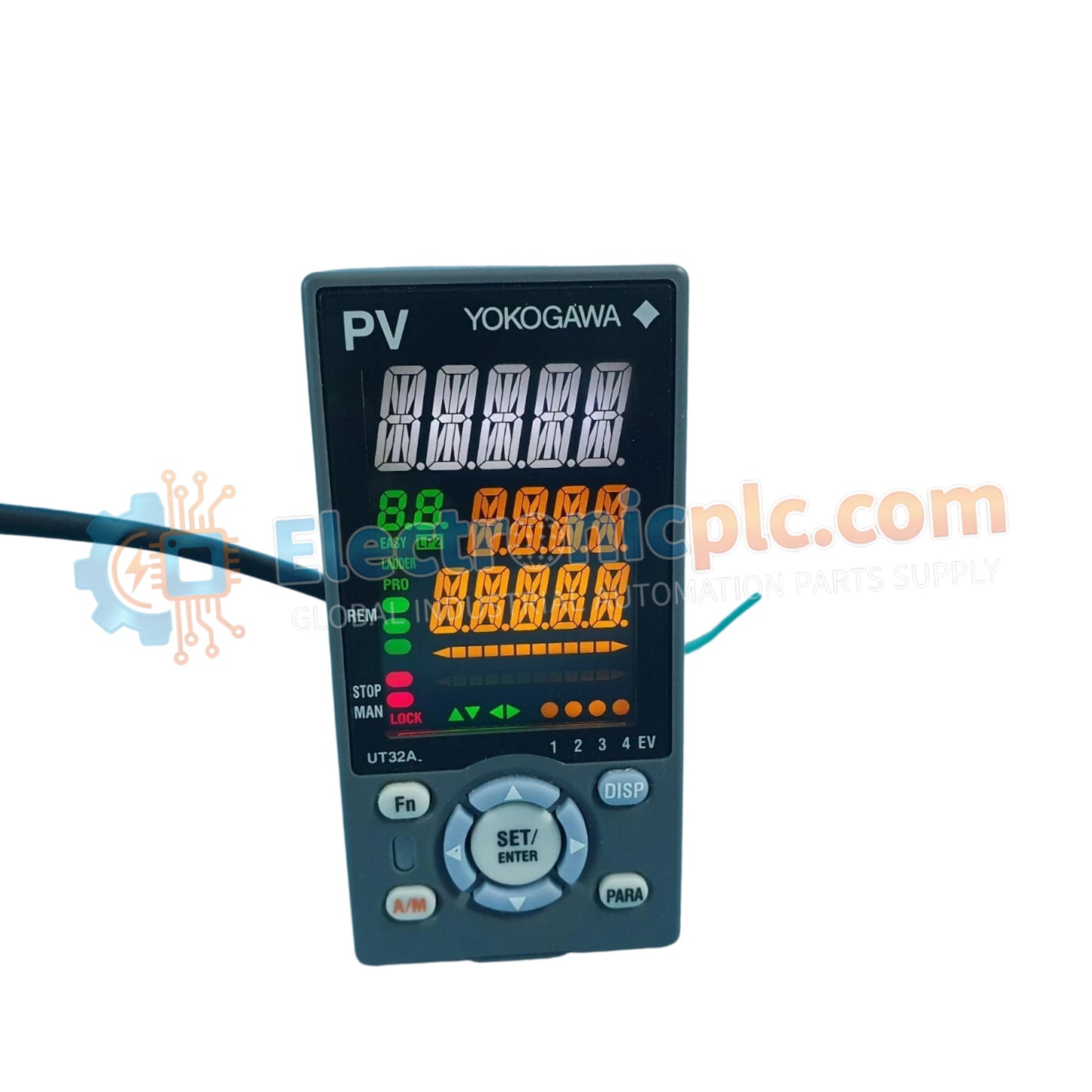
El Yokogawa UT32A-010-11-00, también catalogado como el Controlador Indicador Digital UT32A, opera como un componente de hardware dedicado para la regulación de temperatura de precisión y la gestión de variables de proceso dentro de los lazos de control industrial.
| Parámetro | Especificación |
|---|---|
| Modelo | UT32A-010-11-00 |
| Marca | Yokogawa |
| Origen | Japón |
| Peso | 0,25 kg |
| Dimensiones | 48 mm x 96 mm x 100 mm |
| Temperatura de Operación | 0 a 50 °C |
| Consumo de Energía | 13 VA máximo |
| Pantalla | LCD a color de 14 segmentos |
| Modos de Control | PID, ON/OFF, Calentamiento/Enfriamiento |
| Comunicación | Compatibilidad con RS-485 / Ethernet |
La integración de las capacidades del protocolo HART de lazo de 4-20 mA dentro de la arquitectura de control de Yokogawa garantiza una interfaz precisa del transmisor. Para entornos de procesos de alta densidad, se mantiene el aislamiento de canal a canal para evitar interferencias por bucles de tierra durante la adquisición de señales analógicas. El controlador utiliza compensación de unión fría (CJC) al interactuar con entradas de termopar para mantener la precisión de la medición en condiciones de temperatura ambiente fluctuantes. Esto asegura que la variable de proceso primaria permanezca estable a pesar de las fluctuaciones en el entorno térmico externo.
P: ¿Puede el UT32A-010-11-00 admitir el intercambio en caliente durante la operación activa?
R: No. La unidad está diseñada para montaje en panel con conexiones de bloque de terminales fijas. Se debe aislar la alimentación antes de retirar el controlador de su carcasa para evitar daños en el circuito.
P: ¿Cómo se configura la alarma de ruptura del calentador para umbrales de carga específicos?
R: La función /HA monitorea la corriente a través de un CT (Transformador de Corriente) externo. Los umbrales se configuran dentro del menú del controlador basándose en la corriente nominal del calentador; una alarma se activa cuando la corriente cae por debajo del punto de ajuste definido, indicando una falla de carga.


