
Carrito
0 artículos
¿Tienes una cuenta?
Inicia sesión para finalizar tus compras con mayor rapidez.
Repuestos originales de automatización | Envío exprés a todo el mundo | Garantía de 12 meses — [Solicite presupuesto]

The Woodward 8250-828, also cataloged as the 8250-828 Pneumatic Actuator, operates as a dedicated hardware component for mechanical positioning and fuel flow control within EG3P governor system networks. The device...
Disponibilidad: Bajas existencias: quedan 6
Entrega confiable a nivel mundial
Garantía de devolución de dinero de 30 días
¿Necesitas más información? Consulta nuestra Política de envíos y reembolsos completa.


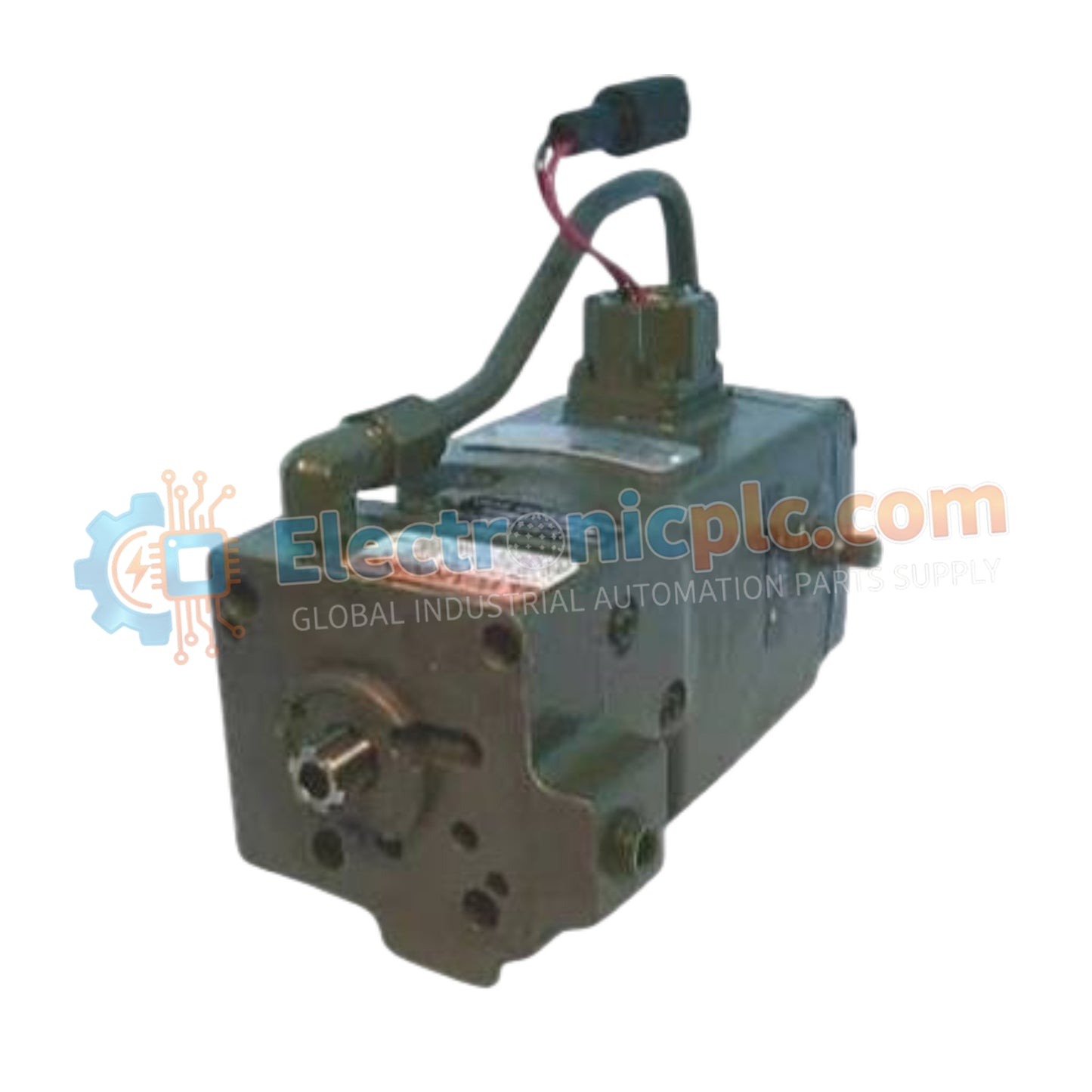
The Woodward 8250-828, also cataloged as the 8250-828 Pneumatic Actuator, operates as a dedicated hardware component for mechanical positioning and fuel flow control within EG3P governor system networks. The device converts pneumatic pressure into proportional mechanical movement utilizing a 24 VDC electrical control signal interface to regulate turbine and engine actuator loops.
| Parameter | Specification |
|---|---|
| Model | 8250-828 |
| Brand | Woodward |
| Origin | USA |
| Weight | 5.5kg |
| Dimensions | Standard EG3P Actuator Frame Layout |
| Operating Temp | -40 deg C to +85 deg C |
| Power Consumption | Standard 24 VDC Control Loop Power |
| Control Voltage | 24 VDC |
| Actuation Method | Pneumatic |
| Compatible System | EG3P Governor Systems |
| Mounting Type | Flange or Bracket Mount |
| Construction | Vibration-resistant heavy-duty industrial enclosure |
The unit utilizes modulated pneumatic pressure combined with 24 VDC electrical position demand signals to achieve fast actuator loop feedback response. In high-speed engine dynamic governor loops, the pneumatic valve linkage provides rapid mechanical force transfer to maintain transient stability. Internal mechanical damping suppresses harmonic distortion under intense operational vibration, preventing position hunting and ensuring deterministic fuel metering calibration across fluctuating load profiles.
Q: What electrical control signal parameters are required to interface with the actuator internal coil assembly?
A: The actuator interface operates on a standard 24 VDC control input line, which must be supplied via a regulated, noise-filtered power circuit to maintain position stability.
Q: How is mechanical mounting established on standard fuel control racks?
A: Physical mounting is executed using standard flange or bracket configurations attached directly to the governor housing, ensuring rigid alignment between the actuator shaft and the valve linkage.
Q: What maintenance steps are recommended to prevent pneumatic linkage binding?
A: The supply air stream must be filtered and regulated to remove oil, moisture, and particulate matter, preventing internal seal degradation and sticky mechanical movement across the operating stroke.


