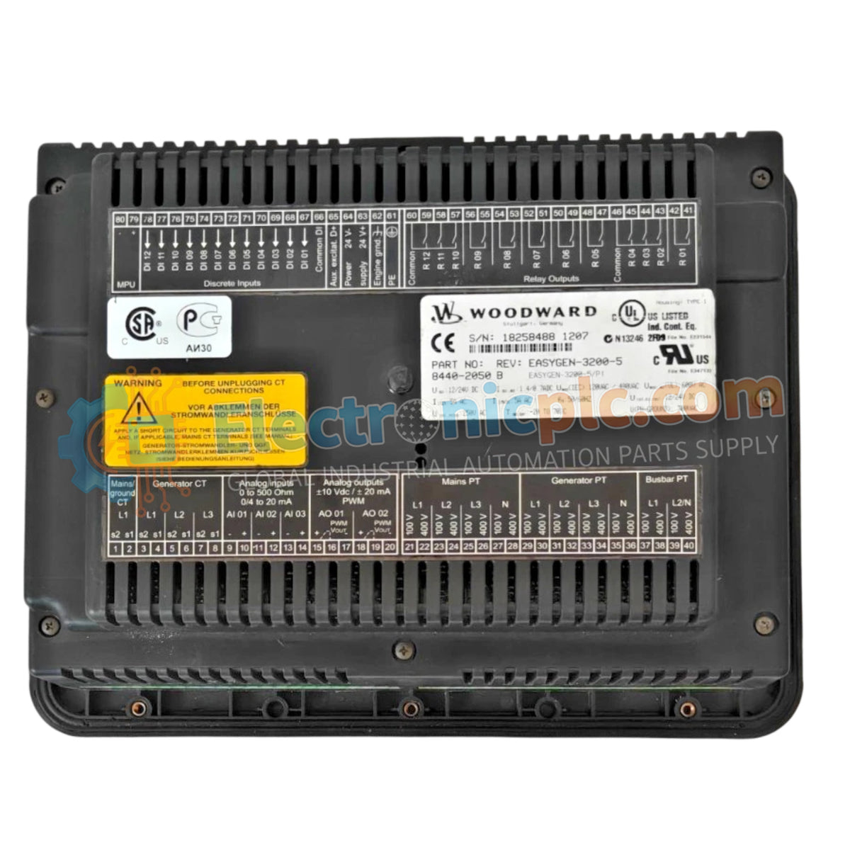
Configured for complex generator management and breaker synchronization in automated power generation systems, the Woodward 8440-2050E (8440-2050E Genset Controller) provides direct physical/electrical execution.
Hardware Specifications
Parameter
Specification
Model
8440-2050E
Brand
Woodward
Origin
USA
Weight
1.6 kg
Dimensions
5 cm x 13 cm x 15 cm
Operating Temp
Standard Industrial Range (-20 to +70 deg C)
Power Consumption
Standard Operating Load
Series
EasyGen Series
Primary Application
Generator Set Control and Protection
Actuator Loop Feedback & Governor Interface
The controller manages engine speed and generator voltage regulation loops through discrete and analog output channels. Actuator loop feedback response directly determines dynamic governing performance, making rapid adjustments to fuel demand signals during load acceptance and shedding. Integrated active power control prevents steady-state hunting and provides harmonic distortion suppression across paralleled genset configurations.
Frequently Asked Questions
Q: How should communication bus wiring be shielded to prevent interference?
A: Communication bus lines require twisted-pair shielded cabling, with shield drain wires connected to a single chassis earth point to prevent ground loop currents.
Q: What wiring separation practices apply inside the switchgear cabinet?
A: Route low-voltage DC power supply cables, sensor inputs, and network communications in separate wireways away from high-current AC power conductors.
Q: What cooling provisions are necessary for continuous duty operation?
A: Heat dissipation relies on natural convection across the metal housing; clear space must be maintained around the controller body inside the switchgear panel.
Field Installation Guidelines
Secure the unit in panel cutouts using specified mounting hardware to resist mechanical vibration.
Connect the main chassis ground point directly to the central switchgear earth busbar using a low-impedance ground strap.
Ensure auxiliary DC power supply lines pass through proper overcurrent protection fuses before connecting to the terminal block.
Confirm line-to-line AC voltage sensing connections match system phase orientation prior to energizing the unit.
¡Obtenga nuestra última actualización!
Únase a nuestra red para obtener cotizaciones exclusivas y noticias del mercado.