
Carrito
0 artículos
¿Tienes una cuenta?
Inicia sesión para finalizar tus compras con mayor rapidez.
Repuestos originales de automatización | Envío exprés a todo el mundo | Garantía de 12 meses — [Solicite presupuesto]

Configurado para la transmisión de datos de alta velocidad en arquitecturas de control distribuido, el YOKOGAWA AIP532/S1 (Módulo Acoplador de Bus ESB AIP532) proporciona ejecución física/eléctrica directa. Este componente de...
Disponibilidad: En existencias
Entrega confiable a nivel mundial
Garantía de devolución de dinero de 30 días
¿Necesitas más información? Consulta nuestra Política de envíos y reembolsos completa.


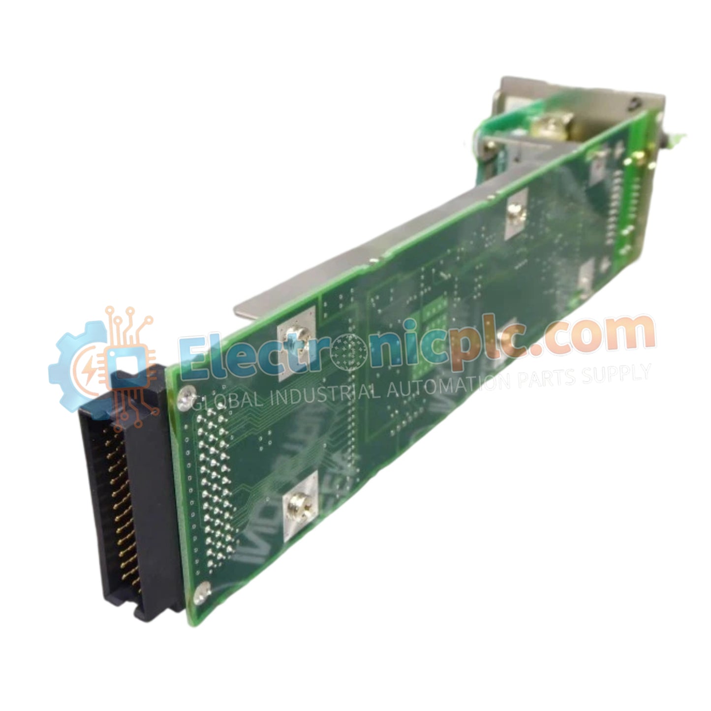
Configurado para la transmisión de datos de alta velocidad en arquitecturas de control distribuido, el YOKOGAWA AIP532/S1 (Módulo Acoplador de Bus ESB AIP532) proporciona ejecución física/eléctrica directa. Este componente de hardware sirve como el acoplador ESB (Enterprise System Bus) principal utilizado para ejecutar una comunicación segura y determinista entre las estaciones de control de campo (FCS) de Yokogawa y las unidades de nodos de E/S remotas a través de plataformas de control industrial.
| Parámetro | Especificación |
|---|---|
| Modelo | AIP532/S1 |
| Marca | YOKOGAWA |
| Origen | JAPÓN |
| Peso | 0,2 kg |
| Dimensiones | 6,3 cm x 6,3 cm x 24,1 cm |
| Consumo de Energía | ≤ 5 W (Típico) |
| Interfaz de Comunicación | Bus ESB |
| Topología de Bus | Punto a Punto / Bus Serie |
El AIP532/S1 actúa como el puente de interfaz dentro de los sistemas de control Yokogawa CENTUM, asegurando un sólido rendimiento de datos entre la Unidad de Control de Campo (FCU) y los nodos de E/S conectados. Gestiona la conversión de señales eléctricas y la integridad de los paquetes en el bus ESB, apoyando los requisitos de sincronización del control de procesos distribuido. Al facilitar la expansión perfecta de la capacidad de E/S, el módulo permite ciclos de escaneo deterministas esenciales para la seguridad y la eficiencia en entornos de automatización industrial complejos.
P: ¿Es el AIP532/S1 compatible con unidades de nodos FIO (Fieldbus I/O) heredadas?
R: El AIP532 está diseñado específicamente para interfaces de comunicación de bus ESB; verifique la compatibilidad de su placa base específica y la revisión de la unidad de nodo en la documentación de Especificaciones Generales (GS) de Yokogawa.
P: ¿Este módulo soporta configuraciones de bus redundantes?
R: Sí, en arquitecturas de bus ESB doblemente redundantes, los módulos AIP532 deben instalarse en pares designados (configuraciones de ranura impar/par) para asegurar una operación continua en caso de una falla de un solo módulo.


