
Carrito
0 artículos
¿Tienes una cuenta?
Inicia sesión para finalizar tus compras con mayor rapidez.
Repuestos originales de automatización | Envío exprés a todo el mundo | Garantía de 12 meses — [Solicite presupuesto]

El Yokogawa KS1-05*A, también catalogado como el cable de señal KS1-05A, funciona como un componente de hardware dedicado para interconectar módulos de E/S a placas de terminales dentro de los...
Disponibilidad: En existencias
Entrega confiable a nivel mundial
Garantía de devolución de dinero de 30 días
¿Necesitas más información? Consulta nuestra Política de envíos y reembolsos completa.
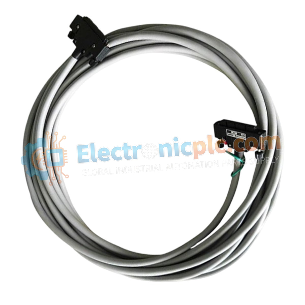
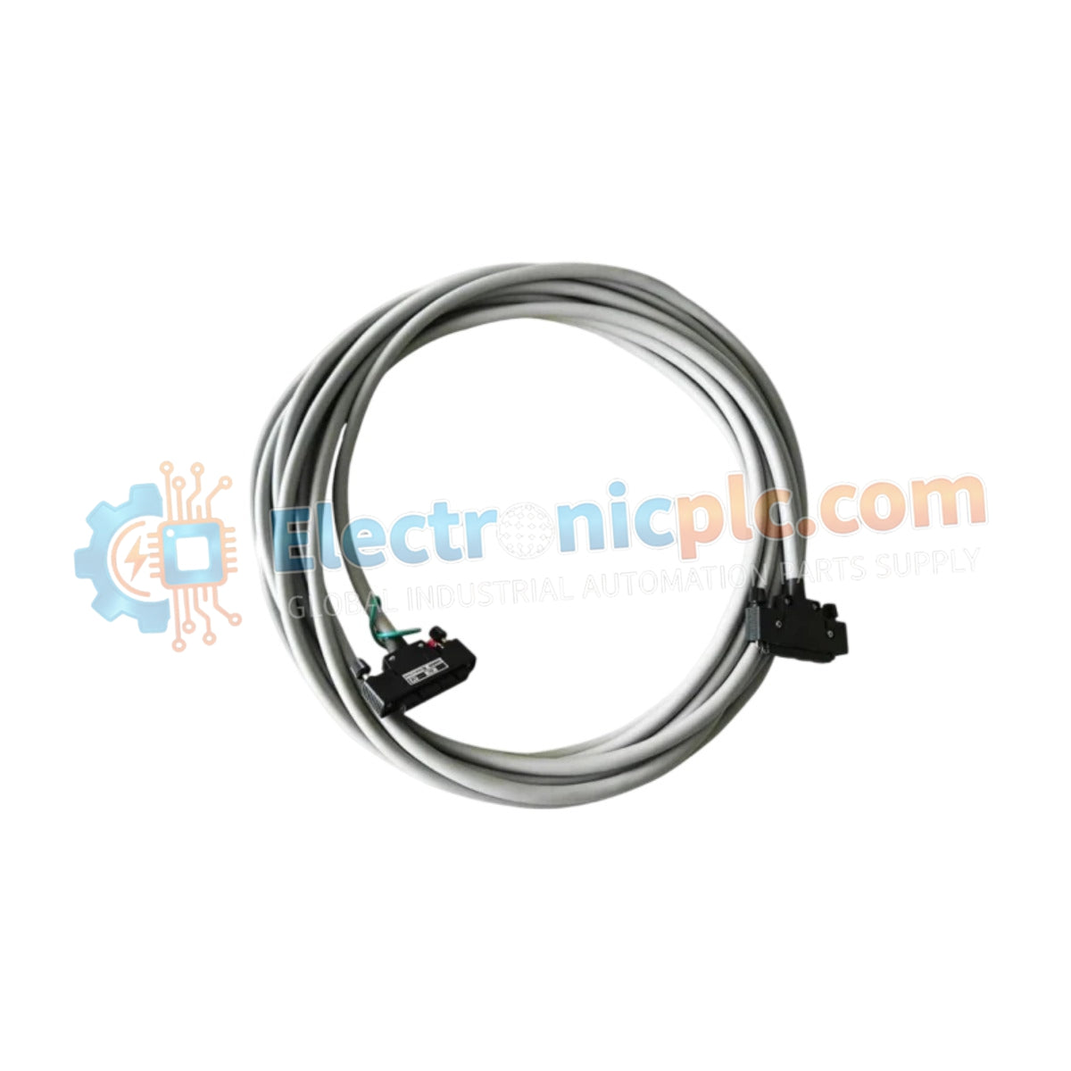
El Yokogawa KS1-05*A, también catalogado como el cable de señal KS1-05A, funciona como un componente de hardware dedicado para interconectar módulos de E/S a placas de terminales dentro de los sistemas de control CENTUM VP y ProSafe-RS.
| Parámetro | Especificación |
|---|---|
| Modelo | KS1-05*A |
| Marca | Yokogawa |
| Origen | Japón |
| Peso | 0.85 kg |
| Dimensiones | 5 m de largo |
| Temperatura de funcionamiento | -20 °C a +70 °C |
| Consumo de energía | No aplicable (componente pasivo) |
| Tipo de conector | De 40 a 40 pines (Estilo A) |
| Material conductor | Cobre estañado, par trenzado |
| Radio de curvatura | 100 mm (mínimo) |
El KS1-05*A utiliza una configuración de blindaje especializada diseñada para mantener la integridad de la señal en entornos industriales sujetos a altas interferencias electromagnéticas (EMI). La implementación de un blindaje resistente a EMI garantiza que las señales analógicas de 4-20 mA o las señales discretas digitales se mantengan dentro de los niveles de tolerancia durante la transmisión desde los conjuntos de terminación de campo hasta el plano posterior de E/S del DCS. La cubierta exterior de PVC ignífugo proporciona protección mecánica para el enrutamiento estacionario en armarios de control.
P: ¿Se puede extender el cable KS1-05*A más allá de su clasificación de 5 metros?
R: No. Extender la longitud del cable más allá de los 5 metros especificados por el fabricante puede introducir caídas de voltaje o desajustes de impedancia inaceptables, lo que podría causar distorsión de la señal en bucles analógicos sensibles.
P: ¿El conector de estilo A admite el intercambio en caliente de módulos de E/S?
R: Si bien el cable en sí no prohíbe el intercambio en caliente, los módulos de E/S y las placas de terminales conectados a través del KS1-05*A deben estar diseñados para la conexión en caliente. Asegúrese de seguir los procedimientos de conexión a tierra adecuados antes de desconectar la interfaz de 40 pines.


