
Carrito
0 artículos
¿Tienes una cuenta?
Inicia sesión para finalizar tus compras con mayor rapidez.
Repuestos originales de automatización | Envío exprés a todo el mundo | Garantía de 12 meses — [Solicite presupuesto]

Configurado para la transmisión de señales de alta integridad en sistemas de control distribuido, el YOKOGAWA KS2-10*B (cable de señal KS2-10*B) proporciona una ejecución física directa del enrutamiento de datos...
Disponibilidad: En existencias
Entrega confiable a nivel mundial
Garantía de devolución de dinero de 30 días
¿Necesitas más información? Consulta nuestra Política de envíos y reembolsos completa.
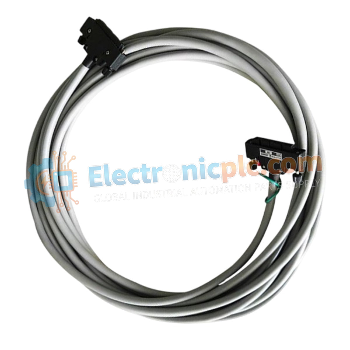
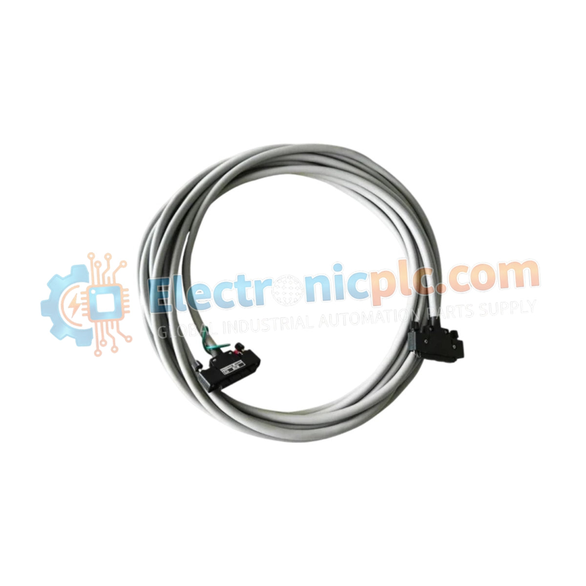
Configurado para la transmisión de señales de alta integridad en sistemas de control distribuido, el YOKOGAWA KS2-10*B (cable de señal KS2-10*B) proporciona una ejecución física directa del enrutamiento de datos entre los módulos de control de campo y los bloques de terminales. El conjunto de cables permite el transporte de señales multicanal a través de arquitecturas de bus V-net, ER bus, ESB bus y RIO bus mediante una interfaz de alta densidad.
| Parámetro | Especificación |
|---|---|
| Modelo | KS2-10*B |
| Marca | YOKOGAWA |
| Origen | Japón |
| Peso | 0,9 kg |
| Dimensiones | 10 metros de largo |
| Temperatura de funcionamiento | Rango industrial estándar |
| Consumo de energía | Pasivo (Ninguno) |
| Tipo de conector | De 40 pines a 40 pines |
| Blindaje | Resistente a EMI |
El cable KS2-10*B está diseñado con blindaje resistente a EMI para mitigar las interferencias electromagnéticas en entornos de control industrial de alta densidad. Si bien el cable actúa como un medio de transmisión pasivo, su geometría interna del conductor está optimizada para mantener una baja diafonía y atenuación de la señal en todo el tramo de 10 metros. El rendimiento del aislamiento de canal a canal está determinado por la integridad de la conexión a tierra de los módulos de control conectados y los conjuntos de terminación de campo. La interfaz de 40 pines garantiza una continuidad pin a pin consistente para grupos de E/S de alta densidad, lo que respalda los requisitos de ancho de banda de los protocolos de señal DCS estandarizados.
P: ¿Se puede acortar o alargar este cable sin comprometer la integridad de la señal?
R: No se recomienda la modificación de la longitud del cable. Cambiar la geometría del cable o la terminación del conector puede introducir desajustes de impedancia y anular la eficacia del blindaje EMI necesario para una comunicación DCS estable.
P: ¿Es este cable adecuado para su uso en armarios industriales de alta vibración?
R: Sí, siempre que el cable esté correctamente enrutado y asegurado con hardware de alivio de tensión para evitar la tensión en los conectores de 40 pines. Asegúrese de que los mecanismos de bloqueo del conector estén completamente acoplados para mantener el contacto eléctrico.


