
Carrito
0 artículos
¿Tienes una cuenta?
Inicia sesión para finalizar tus compras con mayor rapidez.
Repuestos originales de automatización | Envío exprés a todo el mundo | Garantía de 12 meses — [Solicite presupuesto]

The Yokogawa SSB401-13 S1 serves as the primary SSB401-13 Optical ESB Bus Repeater Module utilized to execute optical signal extension and bus isolation across distributed control system platforms.
Disponibilidad: Bajas existencias: quedan 50
Entrega confiable a nivel mundial
Garantía de devolución de dinero de 30 días
¿Necesitas más información? Consulta nuestra Política de envíos y reembolsos completa.


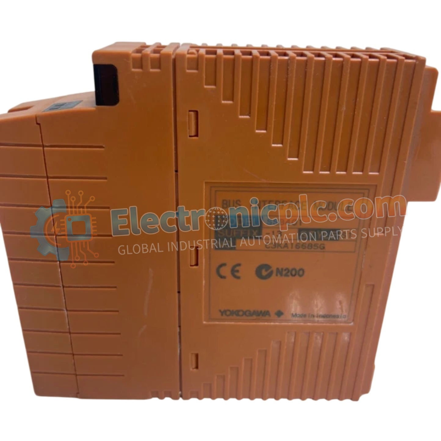
The Yokogawa SSB401-13 S1 serves as the primary SSB401-13 Optical ESB Bus Repeater Module utilized to execute optical signal extension and bus isolation across distributed control system platforms.
| Parameter | Specification |
|---|---|
| Model | SSB401-13 S1 |
| Brand | Yokogawa |
| Origin | Japan |
| Weight | 0.9 kg |
| Dimensions | 5.1 cm x 20.3 cm x 14.6 cm |
| Operating Temp | 0 deg C to 50 deg C |
| Power Consumption | 5 VDC, 0.8 A max |
| Enclosure Type | Rack-mountable module |
The module governs optical data transmission across extended node distances by converting electrical bus signals into optical pulses. System integrity depends on optical transceiver synchronization, ensuring that propagation delay remains within deterministic threshold limits across extended ESB bus loops. Galvanic isolation between local node backplanes and remote fiber-optic segments prevents ground loop propagation and electromagnetic interference common in heavy industrial process environments. Diagnostic monitoring registers optical link attenuation status and generates hardware interrupt signals upon detecting signal degradation or fiber-optic continuity loss.
Q: What are the restrictions regarding hot-swapping the SSB401-13 S1 module?
A: Hot-swapping is restricted unless system power is explicitly cycled or node redundancy configuration permits active online replacement without triggering a controller fault state.
Q: How does the module handle fiber-optic link attenuation thresholds?
A: The internal optical receiver monitors signal strength continuously and flags an error state via backplane status registers if attenuation exceeds permissible link budget margins.
Mount the module securely into the designated node rack slot, ensuring physical alignment with backplane connectors before engaging retention screws. Route fiber-optic cables with minimum bend radii exceeding manufacturer specifications to prevent micro-bending signal loss. Verify optical connector cleanliness using isopropyl alcohol wipes prior to mating patch cords. Terminate cable shielding and grounding drain wires directly to the designated industrial cabinet ground bar to maintain electromagnetic compatibility.


