
Carrito
0 artículos
¿Tienes una cuenta?
Inicia sesión para finalizar tus compras con mayor rapidez.
Repuestos originales de automatización | Envío exprés a todo el mundo | Garantía de 12 meses — [Solicite presupuesto]

Configurado para el acondicionamiento de señal de precisión en plataformas de control industrial, el YOKOGAWA VJSS-L17-AAN0 (Aislador de señal VJSS-L17-AAN0) proporciona aislamiento y conversión directos de señales físicas para lazos...
Disponibilidad: En existencias
Entrega confiable a nivel mundial
Garantía de devolución de dinero de 30 días
¿Necesitas más información? Consulta nuestra Política de envíos y reembolsos completa.

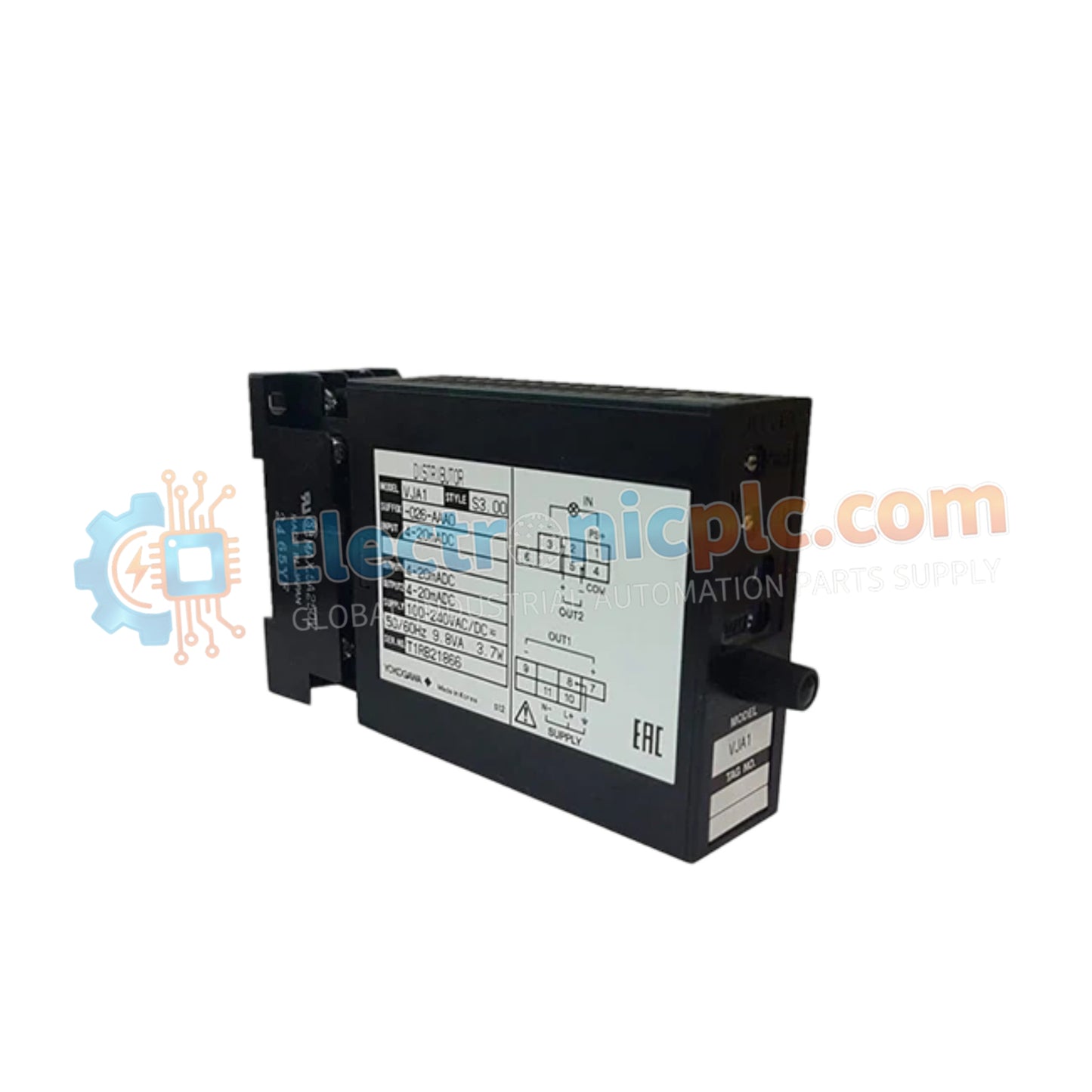
Configurado para el acondicionamiento de señal de precisión en plataformas de control industrial, el YOKOGAWA VJSS-L17-AAN0 (Aislador de señal VJSS-L17-AAN0) proporciona aislamiento y conversión directos de señales físicas para lazos de instrumentación de la serie VJ.
| Parámetro | Especificación |
|---|---|
| Modelo | VJSS-L17-AAN0 |
| Marca | YOKOGAWA |
| Origen | Japón |
| Peso | 0,15 kg |
| Dimensiones | Factor de forma de módulo enchufable |
| Temp. de Operación | -10 a 55 grados C |
| Consumo de Energía | 24 VDC nominales |
| Señal de Entrada | Entrada de lazo de proceso estándar |
| Señal de Salida | Salida de lazo de proceso aislado |
| Aislamiento | Entrada, salida y fuente de alimentación |
El VJSS-L17-AAN0 emplea circuitos avanzados para asegurar el aislamiento eléctrico entre la entrada de campo y la salida del sistema de instrumentación. Esta arquitectura es crítica para gestionar las diferencias de potencial de tierra y prevenir el ruido de la señal en redes de control de procesos a gran escala. La unidad mantiene una estricta linealidad de la señal, asegurando que los datos del protocolo de lazo HART de 4-20 mA se transmitan a través del aislador con una atenuación mínima, preservando así la precisión de la variable de proceso antes de que llegue al procesador de control o al dispositivo de registro.
P: ¿Es compatible este aislador con instalaciones en áreas peligrosas?
R: El VJSS-L17-AAN0 está diseñado para entornos industriales estándar. La compatibilidad con los requisitos de seguridad intrínseca (Ex i) depende de códigos de sufijo específicos no presentes en este modelo; consulte la etiqueta del producto para verificar la certificación.
P: ¿Cómo se debe configurar el módulo para la calibración del rango de entrada?
R: La serie VJSS cuenta con potenciómetros de cero y span ajustables en campo accesibles a través del panel frontal, lo que permite una calibración precisa sin necesidad de retirar el módulo de la base de montaje.

