
My Cart
0 items
Genuine Automation Parts | Worldwide Express Delivery | 12-Month Warranty — [GET A QUOTE]

Configured for slip frequency synchronization, voltage matching, and speed biasing in multi-generator networks, the WOODWARD 8440-1878 (8440-1878 DSLC-2 Digital Synchronizer and Load Control) provides direct physical/electrical execution.
Availability: Low stock: 6 left
Reliable Worldwide Delivery
30-Day Money-Back Guarantee
Need more details? Read our fullShipping PolicyandRefund Policy.


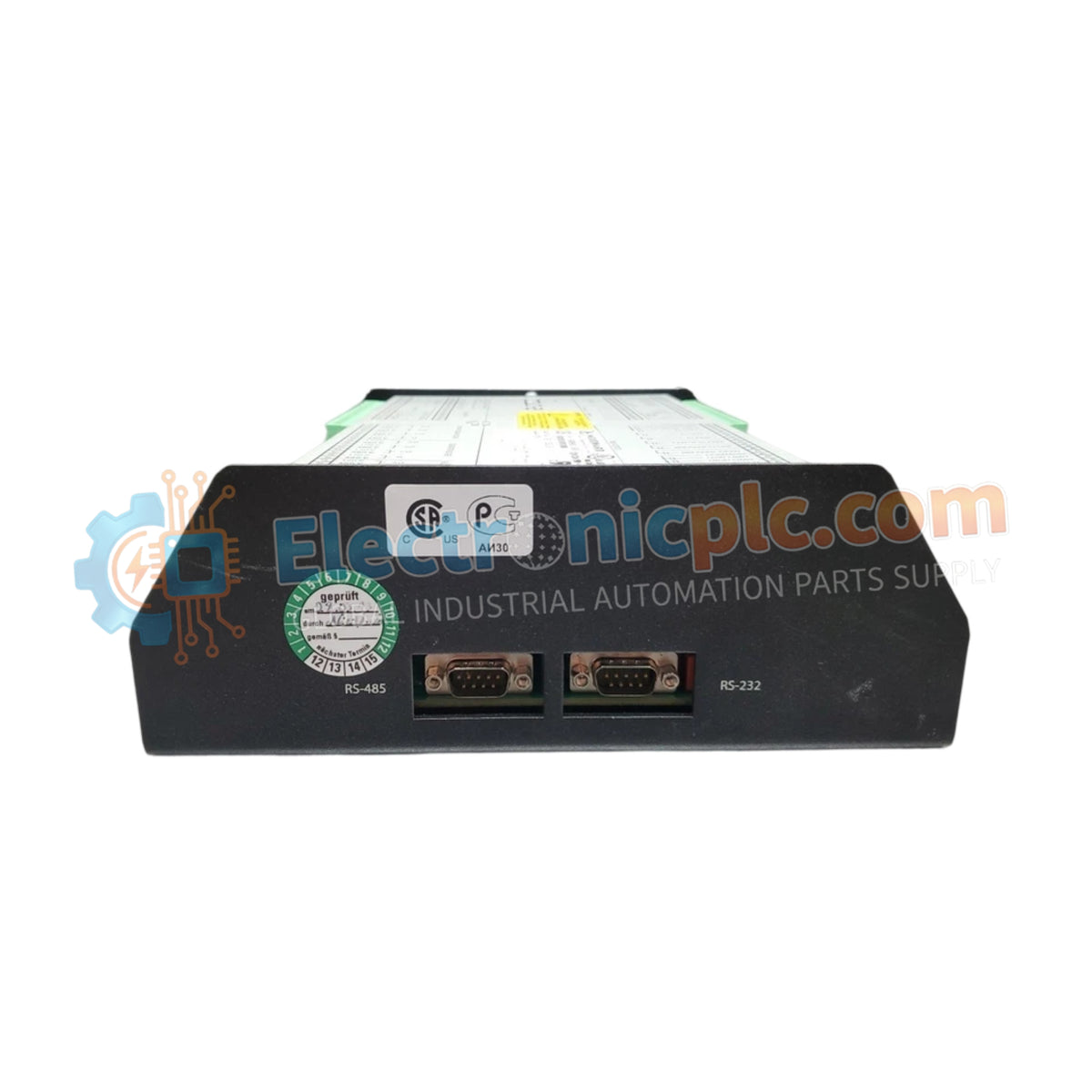
Configured for slip frequency synchronization, voltage matching, and speed biasing in multi-generator networks, the WOODWARD 8440-1878 (8440-1878 DSLC-2 Digital Synchronizer and Load Control) provides direct physical/electrical execution.
| Parameter | Specification |
|---|---|
| Model | 8440-1878 |
| Brand | WOODWARD |
| Origin | USA |
| Weight | 1.34 kg (2.95 lbs) |
| Dimensions | 250 x 227 x 84 mm (9.84 x 9.00 x 3.30 in) |
| Operating Temp | -40 to 70 deg C |
| Power Consumption | Maximum 15 W |
| Input Voltage | 12 / 24 VDC nominal (8 to 40 VDC operational range) |
| CT Input Rating | 5 A secondary |
| Bus Voltage Rating | 120 VAC / 480 VAC |
| Digital I/O Voltage | 12 / 24 VDC inputs and relay outputs |
| Communication Ports | Redundant Ethernet, Multiple Serial Interfaces |
The processing logic continuously samples phase-angle, voltage amplitude, and 5 A CT current feedback across three-phase generator buses. By calculating real-time slip frequency deviations, the module outputs dynamic speed and voltage bias signals directly to the speed governing loop. This maintains high actuator loop feedback response during automatic breaker closing sequences, preventing transient reverse power trips and mechanical shaft stress.
Q: How does the power supply handle low-voltage transients during engine cranking?
A: The wide DC input range of 8 to 40 VDC enables continuous operation during battery voltage dips down to 8 VDC without resetting the processor or interrupting network synchronization data.
Q: What precautions apply when connecting the 5 A CT secondary current loops?
A: All CT secondary connections must remain securely terminated to low-impedance terminals. An open-circuit 5 A CT secondary creates high inductive voltage spikes that can destroy input measurement circuitry.


