
My Cart
0 items
Genuine Automation Parts | Worldwide Express Delivery | 12-Month Warranty — [GET A QUOTE]

The Woodward 9907-173, also cataloged as the 9907-173 Load Sharing Module, operates as a dedicated hardware component for isochronous and droop load balancing within parallel generator control systems. The module...
Availability: Low stock: 6 left
Reliable Worldwide Delivery
30-Day Money-Back Guarantee
Need more details? Read our fullShipping PolicyandRefund Policy.


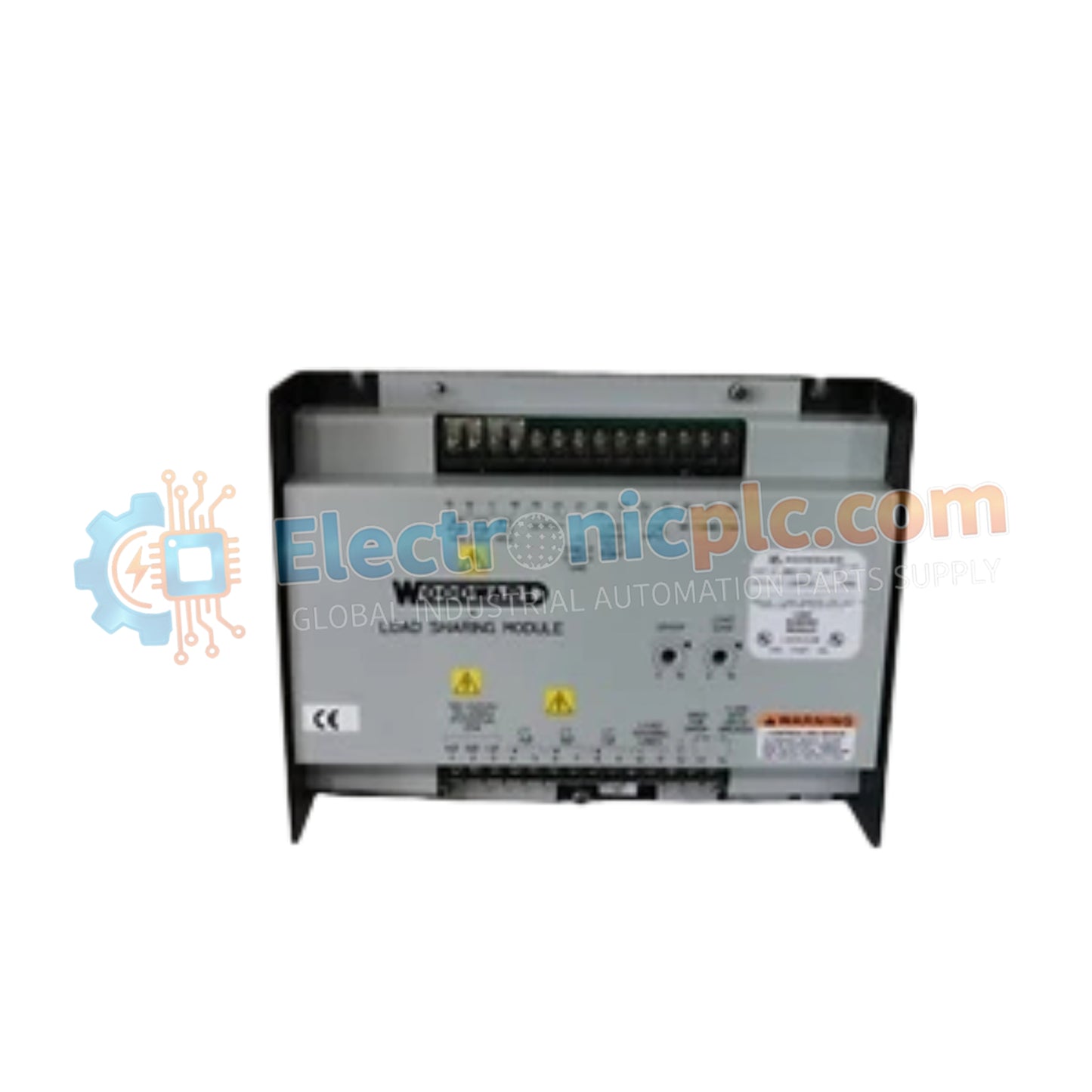
The Woodward 9907-173, also cataloged as the 9907-173 Load Sharing Module, operates as a dedicated hardware component for isochronous and droop load balancing within parallel generator control systems. The module senses 3-phase potential transformer (PT) and current transformer (CT) signals from generator buses, generating a +/-3 VDC analog bias output signal to modulate speed governors and balance active real power distribution across multiple paralleled prime movers.
| Parameter | Specification |
|---|---|
| Model | 9907-173 |
| Brand | Woodward |
| Origin | USA |
| Weight | 2.5 kg |
| Dimensions | 273.6 mm x 59.2 mm x 214.1 mm |
| Operating Temp | -40 deg C to +60 deg C |
| Power Consumption | 5 W approximately |
| Power Supply | 115/230 VAC (95-130 VAC or 190-260 VAC), 50-400 Hz |
| PT Inputs | 3-phase, 100-240 VAC line-to-line |
| CT Inputs | 3-phase, 3-7 Arms at full load |
| Analog Output | +/-3 VDC |
| Droop Range | 0 to 10% speed reduction |
| Environmental Rating | IP54, up to 95% RH (non-condensing) |
| Shock Resistance | 40 g |
| Mounting | Panel-mounted |
The Woodward 9907-173 computes total generator active power by processing instantaneous line voltage and current transformer inputs across a 50 Hz to 400 Hz frequency range. Internal analog control loops dynamically calculate load differentials relative to the paralleling bus, adjusting the +/-3 VDC output to optimize actuator loop feedback response. This direct speed control biasing maintains tight power balance during load step transients without introducing system oscillation.
Q: How is the power supply voltage range configured on the Woodward 9907-173 module?
A: Terminal connections allow field selection between 115 VAC nominal (95-130 VAC operating band) and 230 VAC nominal (190-260 VAC operating band) power inputs across a 50 Hz to 400 Hz frequency spectrum.
Q: What are the primary sensing transformer ratings required for proper operation?
A: The sensing stage accepts 3-phase line-to-line PT inputs between 100 VAC and 240 VAC, paired with 3-phase CT secondary current inputs rated for 3 Arms to 7 Arms at maximum generator output.
Q: What range of droop speed regulation is supported when operating in droop mode?
A: The integrated droop potentiometer circuitry allows adjustment of generator speed reduction from 0% (isochronous operation) up to a maximum 10% speed droop for parallel utility grid operation.


