My Cart
0 items
Genuine Automation Parts | Worldwide Express Delivery | 12-Month Warranty — [GET A QUOTE]

Designed for robust signal distribution within Field Control Station (FIO) architectures, the YOKOGAWA A1BA4D-05 (A1BA4D-05) provides a reliable, DIN-rail mountable interface between field instrumentation and the DCS I/O modules. This...
Availability: Low stock: 99 left
Reliable Worldwide Delivery
30-Day Money-Back Guarantee
Need more details? Read our fullShipping PolicyandRefund Policy.


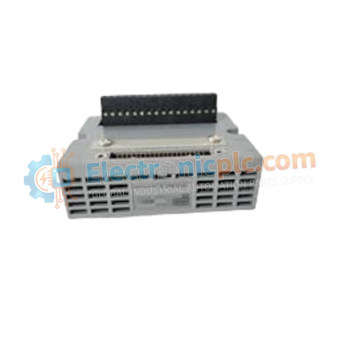
Designed for robust signal distribution within Field Control Station (FIO) architectures, the YOKOGAWA A1BA4D-05 (A1BA4D-05) provides a reliable, DIN-rail mountable interface between field instrumentation and the DCS I/O modules. This terminal board is engineered to manage analog signal connectivity for high-density I/O clusters, supporting both single and dual-redundant configurations.
| Parameter | Specification |
|---|---|
| Model | A1BA4D-05 |
| Brand | Yokogawa |
| Origin | Subject to manufacturing batch |
| Weight | 0.3 kg |
| Mounting Type | DIN rail mount |
| Channels | 16-channel x 1 or 8-channel x 1 |
| Configuration | Single and dual-redundant supported |
| Function | Analog signal termination |
The A1BA4D-05 ensures signal integrity by providing a structured, low-impedance termination point for field wiring. Its modular design allows for rapid installation and maintenance within FIO cabinets, facilitating the transition of field signals—such as 4-20 mA loops or voltage inputs—into the control system. By accommodating both single and dual-redundant cabling, the board supports high-availability process loops where failure of a single path must not compromise control or monitoring functionality.
Q: Does the A1BA4D-05 require specific tools for wiring?
A: The board utilizes standard screw-type terminals. Ensure the use of calibrated screwdrivers and appropriate wire ferrules to maintain secure connections that can withstand industrial vibration.
Q: Is this board compatible with both 8-channel and 16-channel modules?
A: Yes, the board is designed to interface with specified FIO analog modules that support either 8-channel or 16-channel densities, provided the internal jumper or configuration settings match the specific module requirements.


