My Cart
0 items
Genuine Automation Parts | Worldwide Express Delivery | 12-Month Warranty — [GET A QUOTE]

The YOKOGAWA A2EE1A-T, also cataloged as the A2EE1A-T ESB Bus Adapter, operates as a dedicated hardware component for signal termination and bus impedance matching within CENTUM VP control systems.
Availability: Low stock: 99 left
Reliable Worldwide Delivery
30-Day Money-Back Guarantee
Need more details? Read our fullShipping PolicyandRefund Policy.
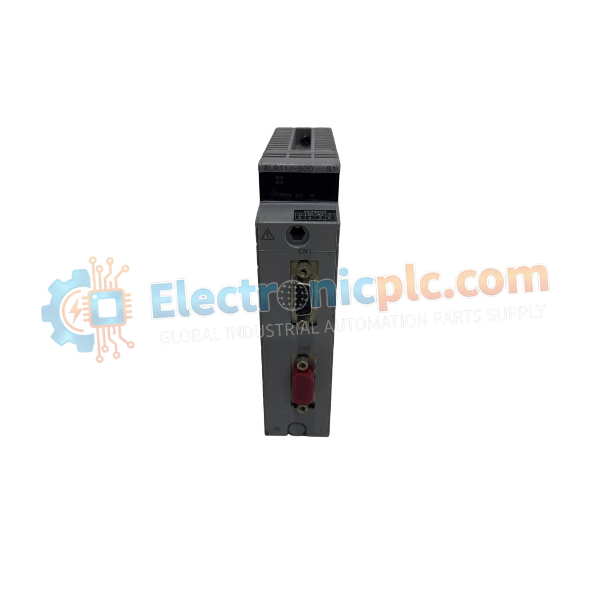

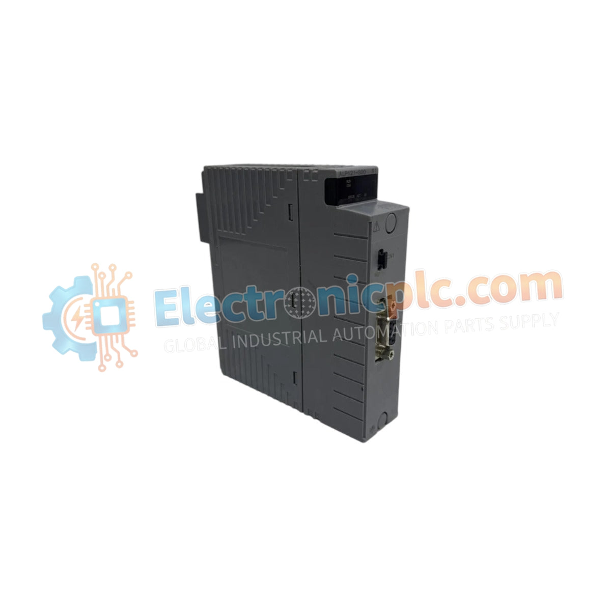
The YOKOGAWA A2EE1A-T, also cataloged as the A2EE1A-T ESB Bus Adapter, operates as a dedicated hardware component for signal termination and bus impedance matching within CENTUM VP control systems.
| Parameter | Specification |
|---|---|
| Model | A2EE1A-T |
| Brand | YOKOGAWA |
| Origin | Japan |
| Weight | 0.3 kg |
| Dimensions | 2.2 x 12.4 x 12.6 cm |
| Operating Temp | Standard industrial range |
| Power Consumption | Passive (Bus powered) |
| System Compatibility | CENTUM VP, FIO Node, Optical ESB Bus Node |
| Function | ESB Bus impedance termination |
The A2EE1A-T adapter maintains network signal integrity by providing active termination at the terminus of the ESB Bus architecture. The internal circuit design is specifically engineered to mitigate signal reflection that occurs at the end of the high-speed data bus, ensuring that the 4-20 mA HART loop protocol environment and digital data packets remain undisturbed. The adapter facilitates galvanic isolation within the bus interface, preventing common-mode noise propagation between field control units and node units. Proper application of this terminator is required to maintain deterministic communication velocity across distributed control platforms, as it stabilizes the transmission line impedance.
Q: Is the A2EE1A-T required at every connection point in the ESB Bus?
A: No. The A2EE1A-T is intended for use specifically at the end of the ESB Bus chain. Installation at intermediate points will disrupt the bus impedance and may cause communication errors.
Q: Can this adapter be used to replace standard ESB cable connectors?
A: No. The A2EE1A-T serves the specific function of bus termination and does not provide passthrough connectivity for standard daisy-chain cabling. It must be installed at the final node connection point.


