
My Cart
0 items
Genuine Automation Parts | Worldwide Express Delivery | 12-Month Warranty — [GET A QUOTE]

Configured for digital output switching in distributed control systems, the YOKOGAWA A2SDV505-S000 (A2SDV505-S000) Digital Output Adaptor provides direct physical and electrical execution for CENTUM VP N-IO platform architectures.
Availability: Low stock: 50 left
Reliable Worldwide Delivery
30-Day Money-Back Guarantee
Need more details? Read our fullShipping PolicyandRefund Policy.


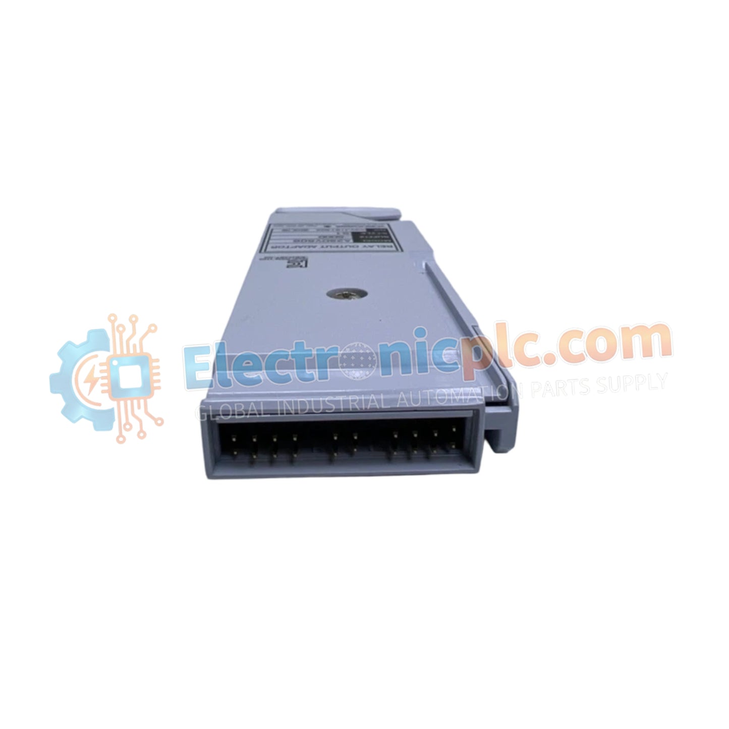
Configured for digital output switching in distributed control systems, the YOKOGAWA A2SDV505-S000 (A2SDV505-S000) Digital Output Adaptor provides direct physical and electrical execution for CENTUM VP N-IO platform architectures.
| Parameter | Specification |
|---|---|
| Model | A2SDV505-S000 |
| Brand | YOKOGAWA |
| Origin | Japan |
| Weight | 0.15kg |
| Dimensions | Compatible with A2BN3D base plate |
| Operating Temp | 0 deg C to 50 deg C |
| Power Supply | 24 VDC plus or minus 10 percent, up to 8.0 A shared |
| Output Type | 24 VDC sourced, non-isolated |
| Maximum Output Current | 0.5 A per channel |
The adaptor incorporates robust galvanic isolation circuitry rated at 1500 V AC between field circuits and system logic, alongside 500 V AC isolation between channels to suppress ground loops and transient surges across multi-loop environments. Signal conditioning stages translate digital control states into 24 VDC sourced outputs for driving field devices such as solenoids and indicator lamps. Internal power distribution tracking continuously monitors shared field power lines up to 8.0 A across adaptor slots, ensuring precise execution within N-IO node networks.
Q: What is the maximum output current supported per channel on the A2SDV505-S000 adaptor?
A: The adaptor delivers up to 0.5 A per channel for driving external field devices.
Q: Which base plate models are compatible with this digital output adaptor?
A: The unit mounts directly onto the A2BN3D base plate within CENTUM VP N-IO units, supporting up to 16 adaptors per base plate.
Mount the A2SDV505-S000 adaptor securely onto the A2BN3D base plate via DIN rail or wall-mounted installation, ensuring proper backplane connector engagement. Terminate field signal cables using pressure clamp or spring clamp terminals supporting wire cross-sections from 0.5 to 2.5 square millimeters, and power wiring from 0.5 to 1.5 square millimeters. Verify field power supply voltage limits and check insulation resistance prior to system energization.


