My Cart
0 items
Genuine Automation Parts | Worldwide Express Delivery | 12-Month Warranty — [GET A QUOTE]

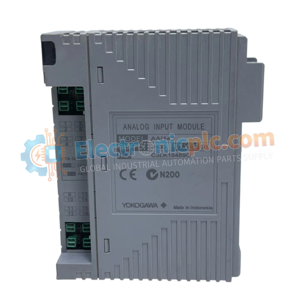
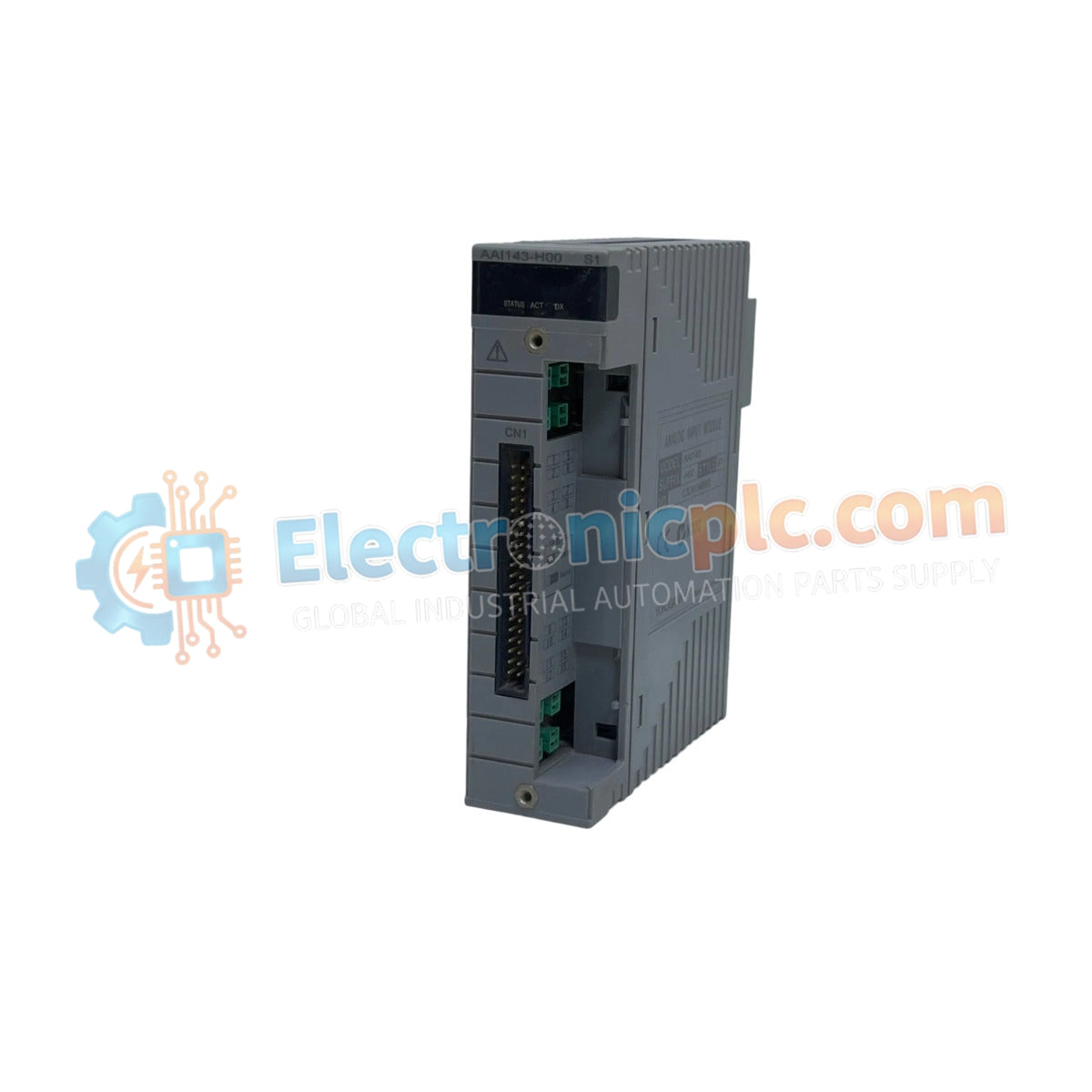
Configured for high-precision signal acquisition in process control networks, the YOKOGAWA AAI143-H00 S1 (AAI143-H00 Analog Input Module) provides direct physical electrical execution for current loop monitoring.
Availability: Low stock: 99 left
Reliable Worldwide Delivery
30-Day Money-Back Guarantee
Need more details? Read our fullShipping PolicyandRefund Policy.

Configured for high-precision signal acquisition in process control networks, the YOKOGAWA AAI143-H00 S1 (AAI143-H00 Analog Input Module) provides direct physical electrical execution for current loop monitoring.
| Parameter | Specification |
|---|---|
| Model | AAI143-H00 S1 |
| Brand | Yokogawa |
| Origin | Japan |
| Weight | 0.18 kg |
| Dimensions | 2.2 cm x 18.1 cm x 12.7 cm |
| Operating Temp | 0 to 50 deg C |
| Power Consumption | Not specified |
The module utilizes channel-to-channel isolation to prevent ground loop interference within the DCS instrumentation architecture. It is engineered to maintain signal delivery accuracy, supporting standard 4-20 mA loop protocols for integration with intelligent field instruments. The internal circuitry is optimized to suppress signal noise, ensuring that input data remains stable under electromagnetic conditions common in high-density process environments.
Q: Does the AAI143-H00 S1 support live removal and insertion?
A: The module is designed for industrial rack-mount environments; verify the specific backplane hot-swap capability and system-level fail-safe requirements before performing removal under energized conditions.
Q: How should I manage the 4-20 mA loop during module maintenance?
A: Ensure that the control loop is transitioned to a manual or safe-hold state within the DCS logic to prevent signal discontinuity or erroneous process data during module replacement.


