My Cart
0 items
Genuine Automation Parts | Worldwide Express Delivery | 12-Month Warranty — [GET A QUOTE]

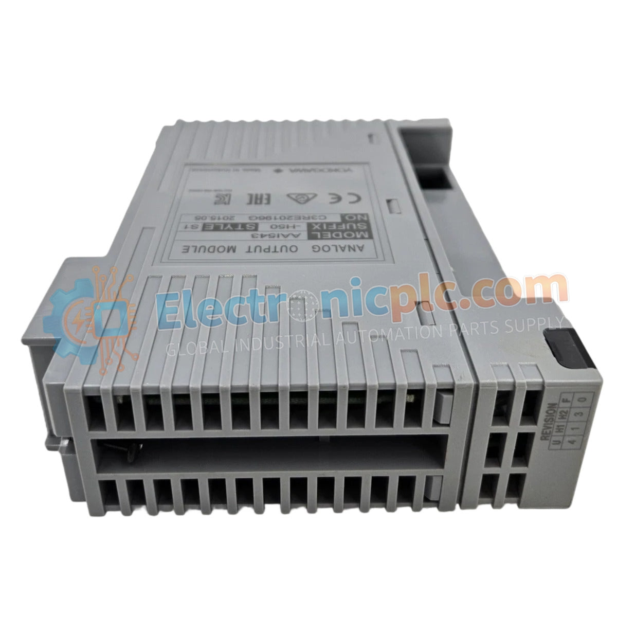
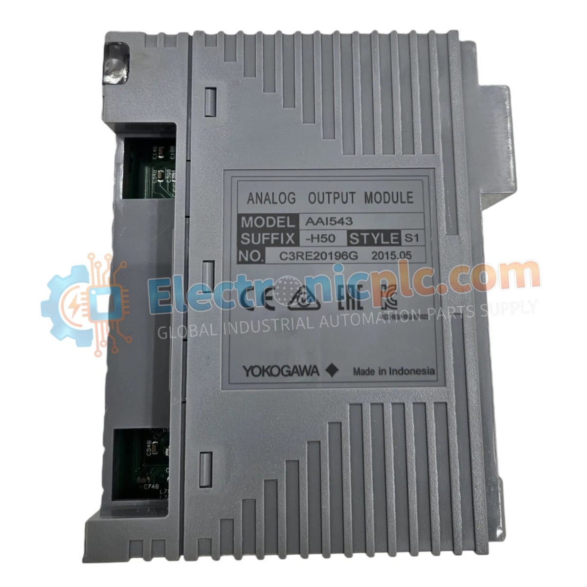
Configured for precision signal conversion in process control networks, the YOKOGAWA AAI543-H50 (AAI543-H50 Analog Output Module) provides direct physical electrical execution for actuator positioning and field device modulation.
Availability: Low stock: 99 left
Reliable Worldwide Delivery
30-Day Money-Back Guarantee
Need more details? Read our fullShipping PolicyandRefund Policy.

Configured for precision signal conversion in process control networks, the YOKOGAWA AAI543-H50 (AAI543-H50 Analog Output Module) provides direct physical electrical execution for actuator positioning and field device modulation.
| Parameter | Specification |
|---|---|
| Model | AAI543-H50 |
| Brand | YOKOGAWA |
| Origin | Janpan |
| Weight | 0.3 kg |
| Dimensions | 12.7 cm x 22.9 cm x 17.8 cm |
| Operating Temp | 0 to 50 deg C |
| Power Consumption | Not specified |
The AAI543-H50 module utilizes channel-to-channel isolation to prevent potential ground loop interference within the DCS instrumentation architecture. It is engineered to maintain high-accuracy output signal delivery, supporting 4-20 mA HART loop protocol integration for seamless communication with intelligent field instruments. The internal circuitry is optimized to suppress signal noise, ensuring that control output remains stable even under electromagnetic conditions common in high-density process environments. Cold junction compensation (CJC) capabilities are utilized where necessary to maintain analog accuracy across all integrated output channels.
Q: Does the AAI543-H50 support live removal and insertion?
A: The module is designed for industrial rack-mount environments; however, verify the specific backplane hot-swap capability and system-level fail-safe requirements before performing removal under energized conditions.
Q: How should I manage the 4-20 mA loop during module maintenance?
A: Ensure that the control loop is transitioned to a manual or safe-hold state within the DCS logic to prevent uncontrolled actuator movement during module replacement.


