My Cart
0 items
Genuine Automation Parts | Worldwide Express Delivery | 12-Month Warranty — [GET A QUOTE]

Configured for high-density signal integration in process control networks, the YOKOGAWA AAI841-S00-S2 (AAI841-S00 Analog Input/Output Module) provides direct physical electrical interface for combined 4-20 mA instrumentation loops and control actuators...
Availability: Low stock: 99 left
Reliable Worldwide Delivery
30-Day Money-Back Guarantee
Need more details? Read our fullShipping PolicyandRefund Policy.
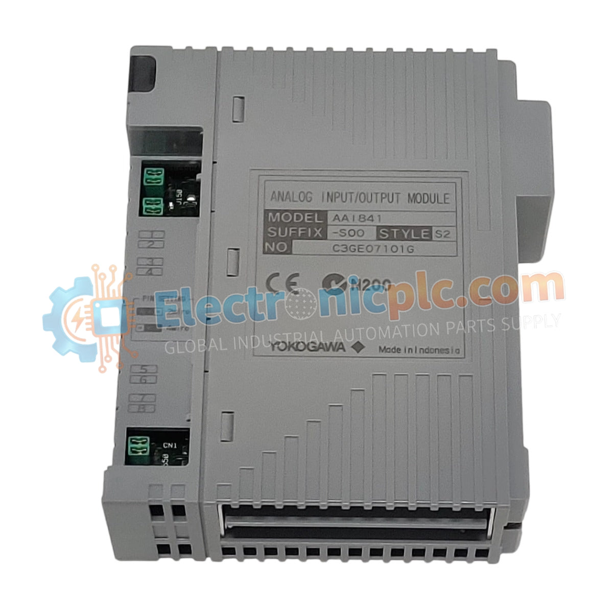
Configured for high-density signal integration in process control networks, the YOKOGAWA AAI841-S00-S2 (AAI841-S00 Analog Input/Output Module) provides direct physical electrical interface for combined 4-20 mA instrumentation loops and control actuators within DCS architectures.
| Parameter | Specification |
|---|---|
| Model | AAI841-S00 S2 |
| Brand | YOKOGAWA |
| Origin | N/A |
| Weight | 0.4 kg |
| Dimensions | N/A |
| Operating Temp | 0 to 50 deg C |
| Power Consumption | Not specified |
| Channels | Combined Input/Output |
| Signal Range | 4 to 20 mA |
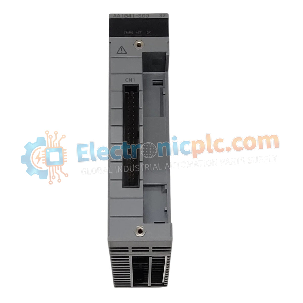
The AAI841-S00 S2 module incorporates channel-to-channel isolation to prevent ground loop interference and common-mode noise propagation throughout the DCS instrumentation bus. It is engineered to support simultaneous 4-20 mA HART loop protocol integration, enabling seamless data communication with field transmitters and actuators. The internal signal conditioning circuits are designed to maintain high accuracy and stability, minimizing signal drift in high-density process environments. Differential input and output stages ensure reliable conversion of analog field signals into digital process values and vice versa.
Q: Does this module support HART protocol communication on all channels?
A: Yes. The AAI841-S00 S2 is designed to support 4-20 mA HART protocol communication, allowing for concurrent analog signal transmission and digital diagnostics with field instruments.
Q: Is this module capable of being removed while the DCS is powered?
A: The module supports standard industrial rack-mount maintenance procedures. Verify the specific backplane hot-swap compatibility and system-level fail-safe requirements in your technical manual prior to performing live removal to prevent process disruption.


