My Cart
0 items
Genuine Automation Parts | Worldwide Express Delivery | 12-Month Warranty — [GET A QUOTE]

Configured for analog signal acquisition in control networks, the Yokogawa AAM11 S1 (AAM11 Current Voltage Input Module) provides direct physical/electrical execution of current and voltage loop processing.
Availability: Low stock: 99 left
Reliable Worldwide Delivery
30-Day Money-Back Guarantee
Need more details? Read our fullShipping PolicyandRefund Policy.
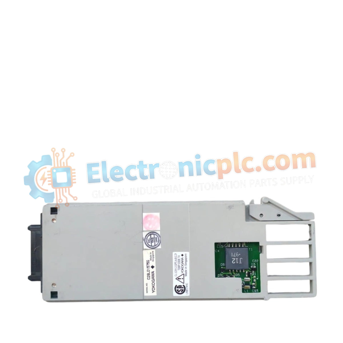
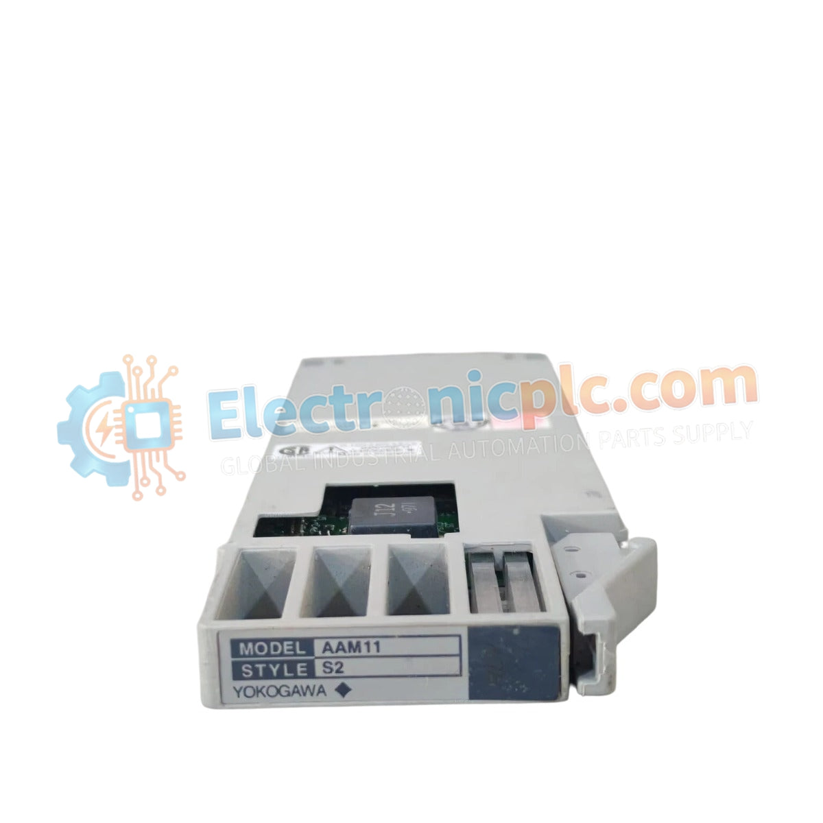
Configured for analog signal acquisition in control networks, the Yokogawa AAM11 S1 (AAM11 Current Voltage Input Module) provides direct physical/electrical execution of current and voltage loop processing.
| Parameter | Specification |
|---|---|
| Model | AAM11 S1 |
| Brand | Yokogawa |
| Origin | Japan |
| Weight | 0.08 kg |
| Dimensions | 16.5 cm x 6 cm x 1 cm |
| Operating Temp | 0 to 50 deg C |
| Power Consumption | 150 mA at 24 VDC |
| Input Channels | Multi-channel configurable |
| Signal Input | Current/Voltage (Software selectable) |
The AAM11 S1 architecture facilitates integration with 4-20 mA HART loop protocol enabled instrumentation. To maintain signal integrity across long-run field cabling, the module incorporates channel-to-channel isolation, preventing ground potential differences from affecting the measurement accuracy. The design prioritizes stable common-mode rejection, ensuring that process variables remain within the defined conversion accuracy thresholds regardless of fluctuations in the field supply voltage.
Q: Does the AAM11 S1 require external loop power for 4-20 mA active transmitters?
A: The module supports both passive and active transmitter configurations; however, internal loop power provisioning is dependent on specific rack bus configuration settings.
Q: Is this module compatible with cold junction compensation (CJC) for thermocouple inputs?
A: This model is designed specifically for current and voltage signal processing and does not feature integrated CJC circuitry for direct thermocouple measurement.


