My Cart
0 items
Genuine Automation Parts | Worldwide Express Delivery | 12-Month Warranty — [GET A QUOTE]

Configured for high-speed signal distribution in CENTUM series control platforms, the YOKOGAWA AAM51-S1 (AAM51-S1 Current/Voltage Output Module) provides direct physical signal conversion from digital control logic to analog field output...
Availability: Low stock: 99 left
Reliable Worldwide Delivery
30-Day Money-Back Guarantee
Need more details? Read our fullShipping PolicyandRefund Policy.
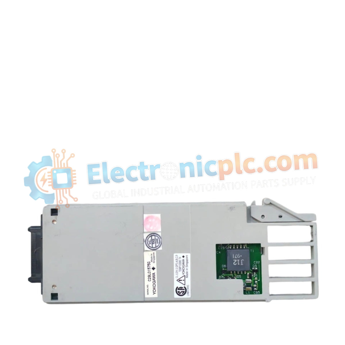
Configured for high-speed signal distribution in CENTUM series control platforms, the YOKOGAWA AAM51-S1 (AAM51-S1 Current/Voltage Output Module) provides direct physical signal conversion from digital control logic to analog field output parameters.
| Parameter | Specification |
|---|---|
| Model | AAM51-S1 |
| Brand | YOKOGAWA |
| Origin | Japan |
| Weight | 0.2 kg |
| Dimensions | 2.2 cm x 12.4 cm x 12.6 cm |
| Operating Temp | 0 to 55 deg C |
| Power Consumption | 5.5 W |
| Signal Capability | Current/Voltage Output |
The module architecture incorporates active galvanic isolation on each output channel to prevent common-mode noise propagation and ground loop formation between the DCS and field-side actuators. It supports standard 4-20 mA HART loop protocol connectivity, enabling bi-directional communication between the controller and field devices such as valves and variable frequency drives. The circuitry utilizes high-precision digital-to-analog converters to maintain output accuracy, ensuring deterministic control response across the system backplane during high-density I/O traffic.
Q: Does the AAM51-S1 support hot-swap functionality during system operation?
A: Yes, the hardware supports insertion and removal while the backplane is energized; however, ensure the corresponding terminal block is configured for high-availability operation to prevent output signal transients during the transition.
Q: How is the output current monitored for fault detection?
A: The module internal logic continuously monitors the loop current; if the circuit opens or the load resistance exceeds the rated driving capacity, the module triggers a fault diagnostic flag to the controller.


