
My Cart
0 items
Genuine Automation Parts | Worldwide Express Delivery | 12-Month Warranty — [GET A QUOTE]

Configured for high-speed pulse signal acquisition in CENTUM CS 3000 and ProSafe-RS platforms, the YOKOGAWA AAP135-S50/13S00 (AAP135 Input Module) provides direct physical/electrical execution for flow measurement, pulse counting, and event detection. This hardware...
Availability: In stock
Reliable Worldwide Delivery
30-Day Money-Back Guarantee
Need more details? Read our fullShipping PolicyandRefund Policy.


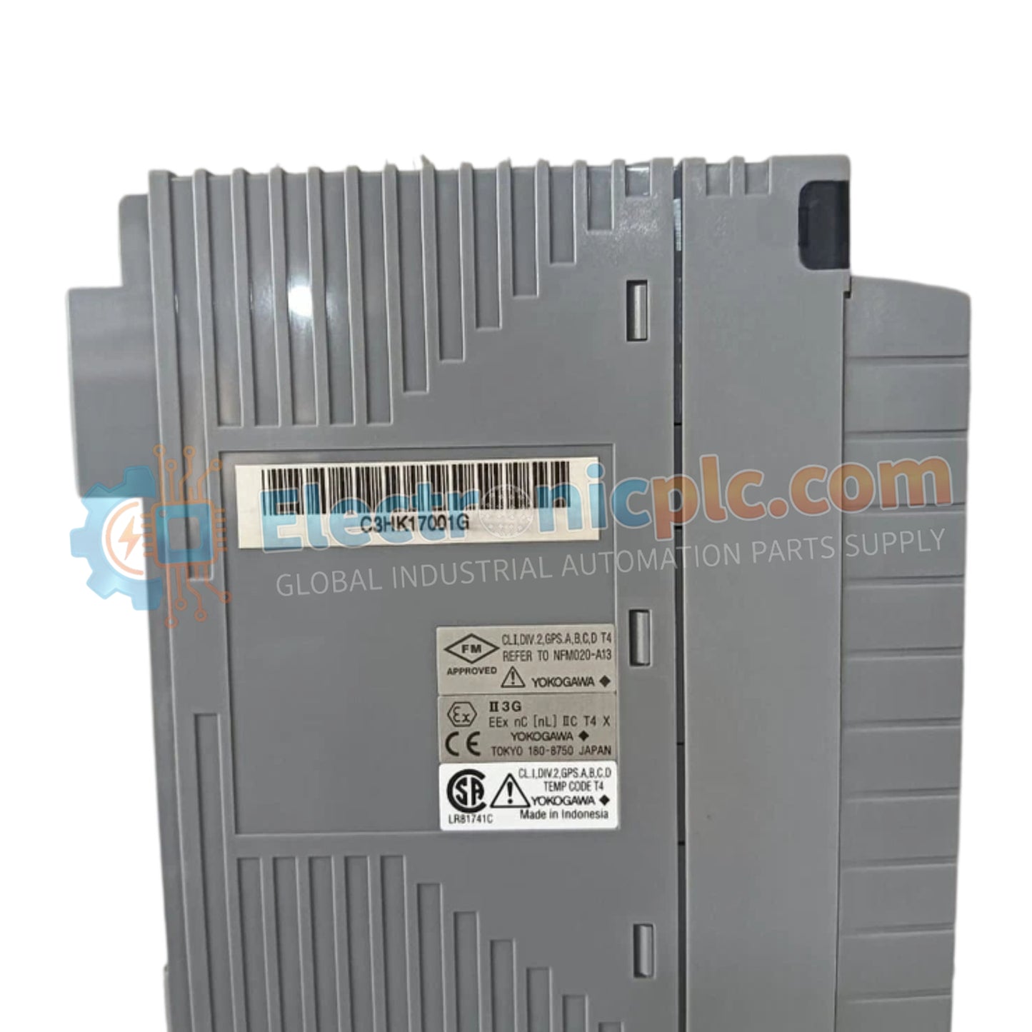
Configured for high-speed pulse signal acquisition in CENTUM CS 3000 and ProSafe-RS platforms, the YOKOGAWA AAP135-S50/13S00 (AAP135 Input Module) provides direct physical/electrical execution for flow measurement, pulse counting, and event detection. This hardware component processes contact ON/OFF, voltage, and current pulse inputs through eight isolated channels.
The AAP135-S50/13S00 represents a specific hardware revision optimized for Yokogawa control architectures:
AAP135: Base model designation for the 8-channel pulse input module.
S50: Specifies the standard operating configuration for DCS and SIS integration.
13S00: Designates the specific versioning and terminal connector arrangement for the module assembly.
| Parameter | Specification |
| Model | AAP135-S50/13S00 |
| Brand | YOKOGAWA |
| Origin | JAPAN |
| Weight | 0.3 kg |
| Dimensions | Standard Module Enclosure |
| Operating Temp | -20 deg C to 70 deg C |
| Power Consumption | 5 V DC (300 mA), 24 V DC (400 mA) |
| Input Channels | 8 (Isolated) |
| Frequency Range | 0 to 10 kHz |
| Data Update Cycle | 2 ms |
The AAP135 module maintains stringent loop integrity for field instrumentation. It supports channel-to-channel isolation with a withstand voltage of 500 V AC, ensuring that common-mode electrical noise does not propagate between channels or into the internal system backplane. This isolation is critical for accurate pulse counting in industrial environments where ground potential differences or high-frequency transients are present.
Q: Can the AAP135-S50/13S00 be used with active 24 V DC field transmitters?
A: Yes, the module provides an internal transmitter power supply of 24 V DC (max 30 mA) or 12 V DC (max 40 mA), allowing for direct connection to many standard field-mounted pulse-generating sensors.
Q: Is the anti-chatter filter adjustable?
A: Yes, the module features configurable signal filtering. This filter can be tuned via system software to suppress bounce or noise on contact inputs, ensuring that only valid transitions are registered by the pulse counter.
Ensure the mounting surface is grounded according to the facility standard to provide a low-impedance path for EMI/RFI discharge from the module housing.
Verify that field wiring polarity is correct for the specific input type (voltage, current, or contact). Incorrect polarity on pulsed inputs may lead to zero counts or signal instability.
Utilize shielded twisted-pair cabling for all pulse input signals to minimize inductive coupling from nearby high-voltage lines. Terminate the shield at the cabinet ground bus only.
When utilizing the internal transmitter power supply, verify that the total load current does not exceed the specified 40 mA (for 12 V DC) or 30 mA (for 24 V DC) per channel.
After physical installation, inspect the isolated screw terminal connections for tightness and ensure no stray wire strands are creating shorts between adjacent terminals.


