Skip to product information
1 of 3

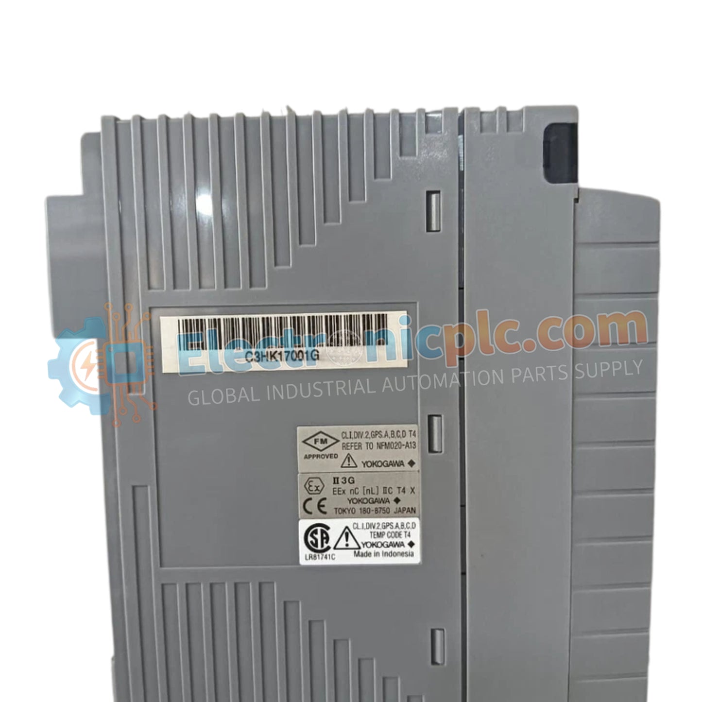
AAV144-S00/A4S00 Analog Input Module Yokogawa

AAV144-S00/A4S00 Analog Input Module Yokogawa

Configured for high-precision monitoring within DCS platforms, the Yokogawa AAV144-S00/A4S00 (AAV144 Analog Input Module) provides direct physical and electrical execution of multi-channel voltage signal acquisition.

Suffix Breakdown & Model Matrix

...
19 people are viewing this right now

AvailabilityIn stock

SKU: AAV144-S00/A4S00
Vendor: Yokogawa
Related Series:

Shipping & Returns

Reliable Worldwide Delivery

  • Carriers: Shipped via DHL, FedEx, UPS, or USPS.
  • Dispatch: Orders processed in 1-2 business days and dispatched within 3-5 business days.
  • Tracking: Full tracking details provided via email upon shipment.

30-Day Money-Back Guarantee

  • Guarantee: 30-day return window for in-stock, factory-sealed products.
  • Condition: Items must be unopened, unused, and in original packaging.
  • Authenticity: We guarantee 100% original and authentic hardware.

Need more details? Read our fullShipping PolicyandRefund Policy.

Authenticity & Warranty

  • Genuine Guarantee: We supply only 100% original, brand-new, and factory-sealed industrial automation parts.
  • Full Coverage: Every component is backed by a 12-month comprehensive warranty from the date of purchase.
  • Traceability: All products come with original factory documentation and accessories for full industrial compliance.

Technical Support & Sourcing

  • Expert Assistance: Our technical team provides free consultation to help you verify compatibility for DCS and PLC systems.
  • Rare Part Sourcing: Specializing in obsolete and hard-to-find components from Allen-Bradley, Siemens, ABB, HIMA, and more.
  • Bulk Inquiries: Contact us at pambo@5gplc.com for volume pricing or customized project quotes.
View full product details

Configured for high-precision monitoring within DCS platforms, the Yokogawa AAV144-S00/A4S00 (AAV144 Analog Input Module) provides direct physical and electrical execution of multi-channel voltage signal acquisition.

Suffix Breakdown & Model Matrix

  • AAV144: Base model designation for the 16-channel analog input module series.
  • S00: Standard configuration code for signal processing and voltage range selection.
  • A4S00: Specifies the interface compatibility and terminal connection hardware for integration into Yokogawa field terminal assemblies.

Hardware Specifications

Parameter Specification
Model AAV144-S00/A4S00
Brand Yokogawa
Origin Japan
Weight 0.2 kg
Dimensions Standard I/O module form factor
Operating Temp -20 deg C to 70 deg C
Power Consumption 500 mA (5 V DC)
Input Channels 16 (isolated)
Signal Range 1 to 5 V, -10 to 10 V
Isolation Voltage 1500 V AC (1 minute)

Signal Processing and Galvanic Isolation

The AAV144-S00/A4S00 implements channel-to-channel isolation through an integrated transformer-coupled architecture, ensuring that the 1500 V AC isolation rating is maintained between field inputs and the DCS system backplane. This isolation design protects the sensitive analog-to-digital conversion circuitry from common-mode noise and ground loops in large-scale process installations. The module facilitates seamless integration with 4-20 mA HART loop protocol signals through the use of external precision shunt resistors, allowing the input stages to process current-based process variables accurately within the defined voltage ranges.

Frequently Asked Questions

Q: Are the input ranges configurable per channel or for the entire module?

A: Input signals for channels CH1 to CH16 are set collectively. Configure the module via the system engineering station software to ensure that the input range (1-5 V or -10 to 10 V) matches the field transmitter output across all channels on the card.

Q: What is the maximum allowable input voltage before permanent damage occurs?

A: The module is designed to withstand an input voltage of up to ±30 V without sustaining internal damage. Exceeding this limit will bypass internal protection circuits and compromise the measurement accuracy or result in total hardware failure.

Field Installation Guidelines

  • Backplane Seating: Ensure the module is properly indexed before insertion into the backplane slot. Use the mechanical locking tabs to secure the module and maintain reliable electrical contact with the system bus.
  • Grounding and Shielding: Terminate all analog signal cable shields at the designated system ground stud on the terminal assembly. Ensure the system ground is low-impedance to maintain the integrity of the 16-channel isolated inputs.
  • Wiring Segregation: Route analog input wiring through dedicated metallic trays, keeping them strictly separated from high-voltage AC lines, relay control wiring, and VFD power cabling to mitigate EMI.
  • Calibration: Given the drift characteristics (up to +/- 20 mV per 10 deg C), ensure the cabinet environment is regulated. Perform periodic loop validation and zero-point verification if the ambient cabinet temperature fluctuates significantly.