My Cart
0 items
Genuine Automation Parts | Worldwide Express Delivery | 12-Month Warranty — [GET A QUOTE]

Configured for high-precision voltage signal acquisition in DCS network platforms, the Yokogawa AAV144-S00/K4A00 (AAV144 Analog Input Module) provides direct physical/electrical execution. This 16-channel component serves as a primary interface for...
Availability: In stock
Reliable Worldwide Delivery
30-Day Money-Back Guarantee
Need more details? Read our fullShipping PolicyandRefund Policy.


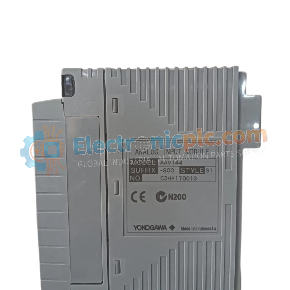
Configured for high-precision voltage signal acquisition in DCS network platforms, the Yokogawa AAV144-S00/K4A00 (AAV144 Analog Input Module) provides direct physical/electrical execution. This 16-channel component serves as a primary interface for processing 1-5 V DC or -10 to +10 V DC inputs, ensuring signal conversion and channel-to-channel isolation within the CENTUM VP or CS 3000 control environments.
| Parameter | Specification |
|---|---|
| Model | AAV144-S00/K4A00 |
| Brand | Yokogawa |
| Origin | Japan |
| Weight | 0.4 kg |
| Dimensions | 108 mm x 34 mm x 130 mm |
| Operating Temp | 0 to 50 deg C |
| Power Consumption | Subject to system backplane supply constraints |
| Input Channels | 16 isolated channels |
| Input Range | 1-5 V DC, -10 to +10 V DC |
| Accuracy | ±4 mV (typical), ±20 mV (max) |
| Update Period | 10 ms |
The module features robust channel-to-channel isolation, which is required to prevent common-mode noise and ground loops in high-density instrumentation arrays. Each channel is configured to handle input ranges up to ±10 V DC, with an allowable voltage limit of ±30 V DC to prevent damage during field faults. The internal design includes a high input resistance (1 MOhm power-on) to ensure minimal loading effect on precision field transducers, maintaining signal integrity across the 10 ms data update cycle.
Q: Does the AAV144-S00 support hot-swapping during system operation?
A: Yes, this module supports hot-swapping within the I/O base unit. Ensure the module is fully latched to the backplane to establish secure electrical contact and bus communication.
Q: Can channels be configured for different input ranges simultaneously?
A: Yes, the module supports channel-by-channel configuration. Parameters can be adjusted via the system engineering software to select between 1-5 V DC and -10 to +10 V DC ranges based on specific field instrument requirements.


