My Cart
0 items
Genuine Automation Parts | Worldwide Express Delivery | 12-Month Warranty — [GET A QUOTE]

Configured for high-precision signal acquisition in Yokogawa control platforms, the YOKOGAWA AAV144-S00/K4A00 (AAV144-S00/K4A00 Analog Input Module) provides direct physical and electrical interface execution for 16 isolated analog voltage channels. This...
Availability: Low stock: 99 left
Reliable Worldwide Delivery
30-Day Money-Back Guarantee
Need more details? Read our fullShipping PolicyandRefund Policy.

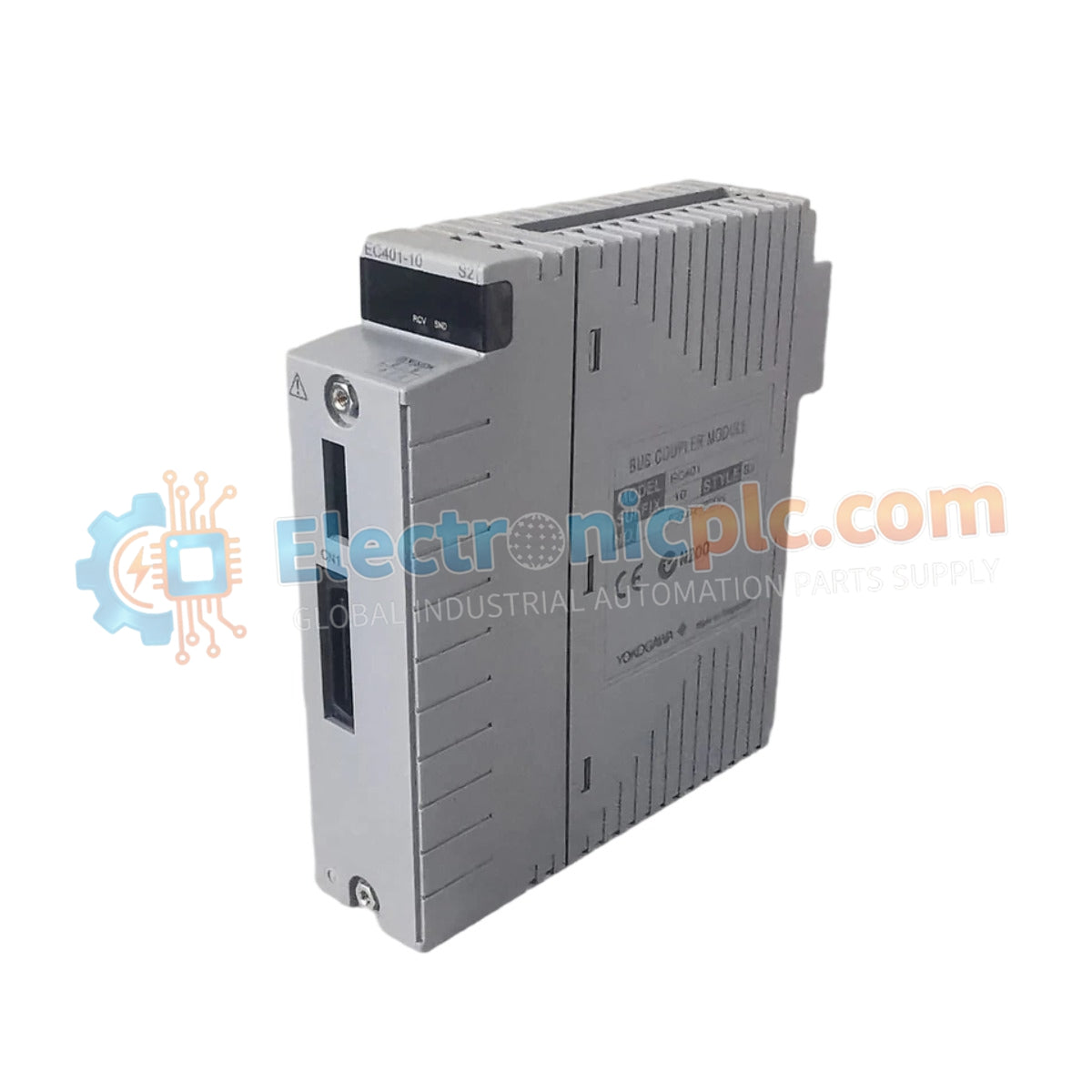
Configured for high-precision signal acquisition in Yokogawa control platforms, the YOKOGAWA AAV144-S00/K4A00 (AAV144-S00/K4A00 Analog Input Module) provides direct physical and electrical interface execution for 16 isolated analog voltage channels. This hardware component manages multi-channel voltage signal processing and data conversion within CENTUM VP and ProSafe-RS distributed control systems.
| Parameter | Specification |
|---|---|
| Model | AAV144-S00/K4A00 |
| Brand | Yokogawa |
| Origin | Subject to manufacturing batch |
| Weight | 0.4 kg |
| Dimensions | 108 mm x 34 mm x 130 mm |
| Operating Temp | Standard industrial ambient range |
| Power Consumption | 500 mA at 5 VDC (from backplane) |
| Input Channels | 16 isolated channels |
| Signal Range | 1-5 VDC, -10 to +10 VDC (configurable) |
| Isolation Voltage | 1500 VAC (1 minute) |
The AAV144-S00/K4A00 provides per-channel isolation to prevent common-mode noise propagation, ensuring high data fidelity for sensitive voltage-based measurements. The module features 1 MΩ input resistance during operation, minimizing loading effects on field instrumentation. With a 10 ms data update period, it provides the deterministic response required for tight process control loops.
Q: Can the AAV144-S00/K4A00 be used for current inputs?
A: The module is optimized for voltage inputs. While the specifications list input impedance for current (250 Ω), utilizing the module for current loops requires appropriate external precision shunt resistors if not integrated into the terminal board.
Q: Does the channel isolation allow for grounded signal sources?
A: Yes, the 1500 VAC channel-to-system isolation permits the connection of field sensors that may be grounded at the source, provided the common-mode voltage remains within the module's safety rating.


