My Cart
0 items
Genuine Automation Parts | Worldwide Express Delivery | 12-Month Warranty — [GET A QUOTE]

Configured for high-density discrete signal switching in ProSafe-RS safety systems, the Yokogawa ADC32 (ADC32 Contact Output Module) provides direct physical/electrical execution of 32-channel relay-based output control.
Availability: In stock
Reliable Worldwide Delivery
30-Day Money-Back Guarantee
Need more details? Read our fullShipping PolicyandRefund Policy.


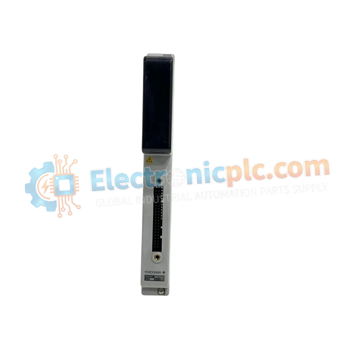
Configured for high-density discrete signal switching in ProSafe-RS safety systems, the Yokogawa ADC32 (ADC32 Contact Output Module) provides direct physical/electrical execution of 32-channel relay-based output control.
| Parameter | Specification |
|---|---|
| Model | ADC32 |
| Brand | Yokogawa |
| Origin | Japan |
| Weight | 0.5 kg |
| Dimensions | 65.6 mm x 72 mm x 52.3 mm |
| Operating Temp | -10 deg C to 55 deg C |
| Power Consumption | Not specified |
| Output Channels | 32 isolated channels |
| Output Type | Relay contact |
| Status Indicator | Channel-specific LED |
The ADC32 is engineered for the ProSafe-RS architecture, prioritizing high-density signal distribution while maintaining individual channel integrity. Each of the 32 channels features galvanic isolation, preventing common-mode noise and ground loops from propagating across the output stage. This isolation is critical for maintaining fault-tolerant logic execution when interfacing with disparate field devices. When configuring the module for sinking or sourcing operations, ensure that the load impedance does not exceed the mechanical relay switching current limits to prevent contact welding and ensure fail-safe state execution during critical system events.
Q: Does the ADC32 support hot-swapping under load? A: No. Any extraction or insertion of the module into the system backplane must be performed only after the rack power is disconnected to prevent terminal arcing and backplane communication corruption.
Q: How do the LED status indicators map to the output state? A: Each channel is equipped with a dedicated LED that provides direct visual verification of the energized status of the relay contact, allowing for immediate field-level diagnostics without requiring a secondary handheld multimeter.


