My Cart
0 items
Genuine Automation Parts | Worldwide Express Delivery | 12-Month Warranty — [GET A QUOTE]

Configured for precise discrete signal acquisition, the Yokogawa ADM12C S2 (ADM12C Digital Input Module) facilitates the monitoring of field-side industrial status indicators within Yokogawa automation architectures, supporting stable data integration...
Availability: Low stock: 99 left
Reliable Worldwide Delivery
30-Day Money-Back Guarantee
Need more details? Read our fullShipping PolicyandRefund Policy.
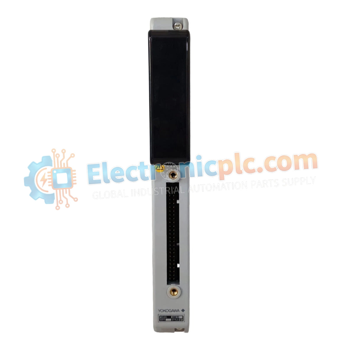

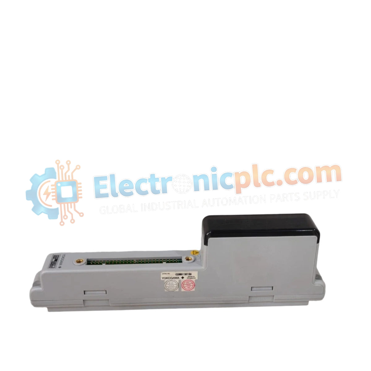
Configured for precise discrete signal acquisition, the Yokogawa ADM12C S2 (ADM12C Digital Input Module) facilitates the monitoring of field-side industrial status indicators within Yokogawa automation architectures, supporting stable data integration via the Modbus RTU communication protocol.
| Parameter | Specification |
|---|---|
| Model | ADM12C S2 |
| Brand | Yokogawa |
| Type | Digital Input Module |
| Input Channels | 12 channels |
| Operating Voltage | 24 VDC |
| Input Current | ≤ 20 mA |
| Protocol | Modbus RTU |
| Dimensions | 82 mm x 82 mm x 35 mm |
| Weight | 0.14 kg (0.31 lbs) |
| Operating Temp | -10 to +55 deg C |
The ADM12C S2 functions as a high-reliability interface that captures discrete states from field sensors and switches. By utilizing the Modbus RTU protocol, the module provides a standard communication path for real-time status updates, ensuring that control systems receive accurate and low-latency input data. This capability is critical for environments requiring consistent monitoring of interlocking safety switches, equipment running status, and process alarm conditions.
Q: Is the ADM12C S2 compatible with non-Modbus industrial controllers?
A: The module is primarily engineered for Modbus RTU communication; while other protocols may be implemented through external gateways, direct integration requires a controller capable of acting as a Modbus Master.
Q: Can the input voltage be adjusted for higher sensitivity?
A: The module is fixed for a 24 VDC nominal input; altering the voltage level outside of the rated specifications will impact the internal opto-isolator trigger thresholds and may lead to module failure.


