My Cart
0 items
Genuine Automation Parts | Worldwide Express Delivery | 12-Month Warranty — [GET A QUOTE]

Configured for discrete signal execution in distributed control networks, the Yokogawa ADM51C-2 (ADM51C-2 Contact Output Module) provides direct physical switching control to field-mounted relays, contactors, and solenoid valves. The ADM51C-2...
Availability: Low stock: 99 left
Reliable Worldwide Delivery
30-Day Money-Back Guarantee
Need more details? Read our fullShipping PolicyandRefund Policy.
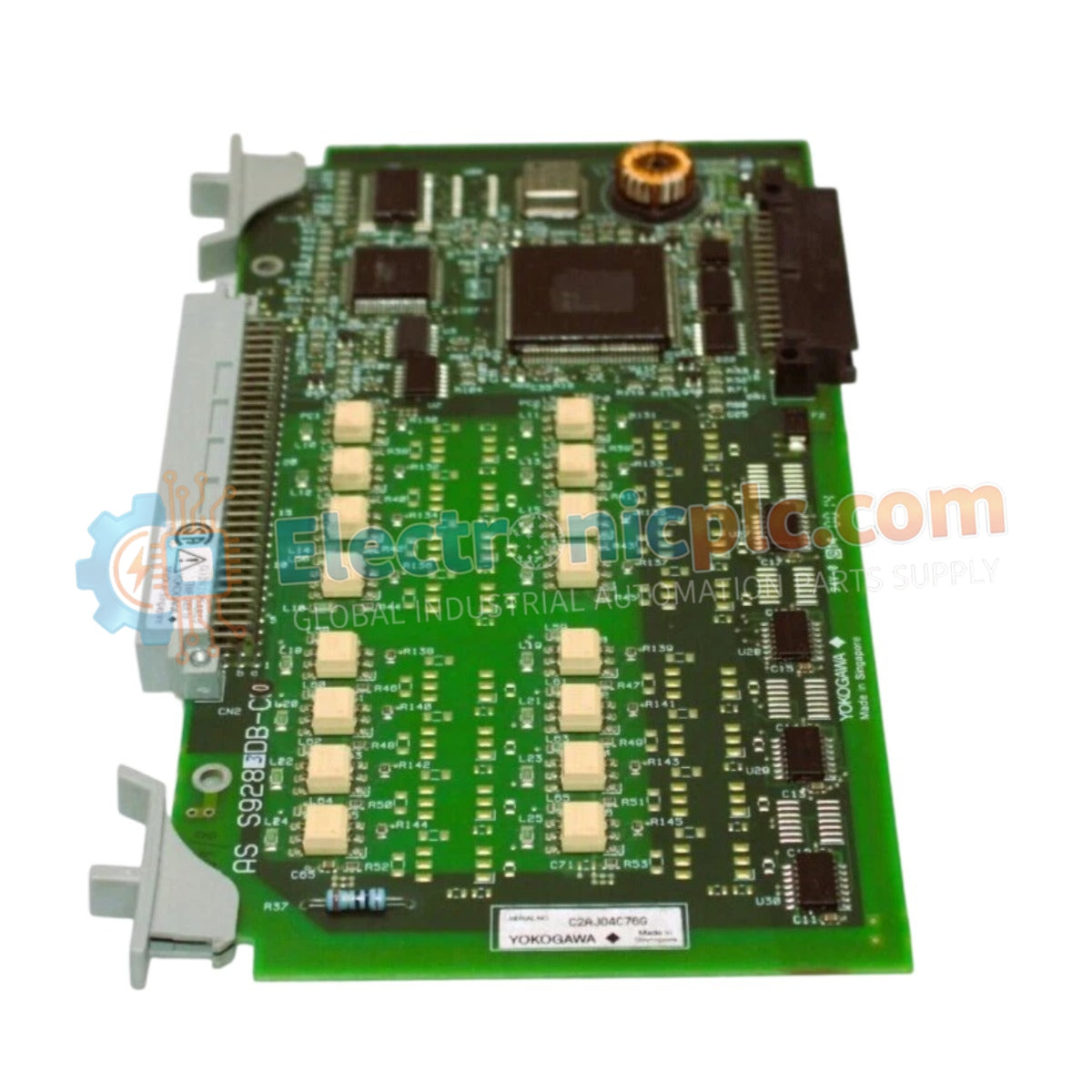

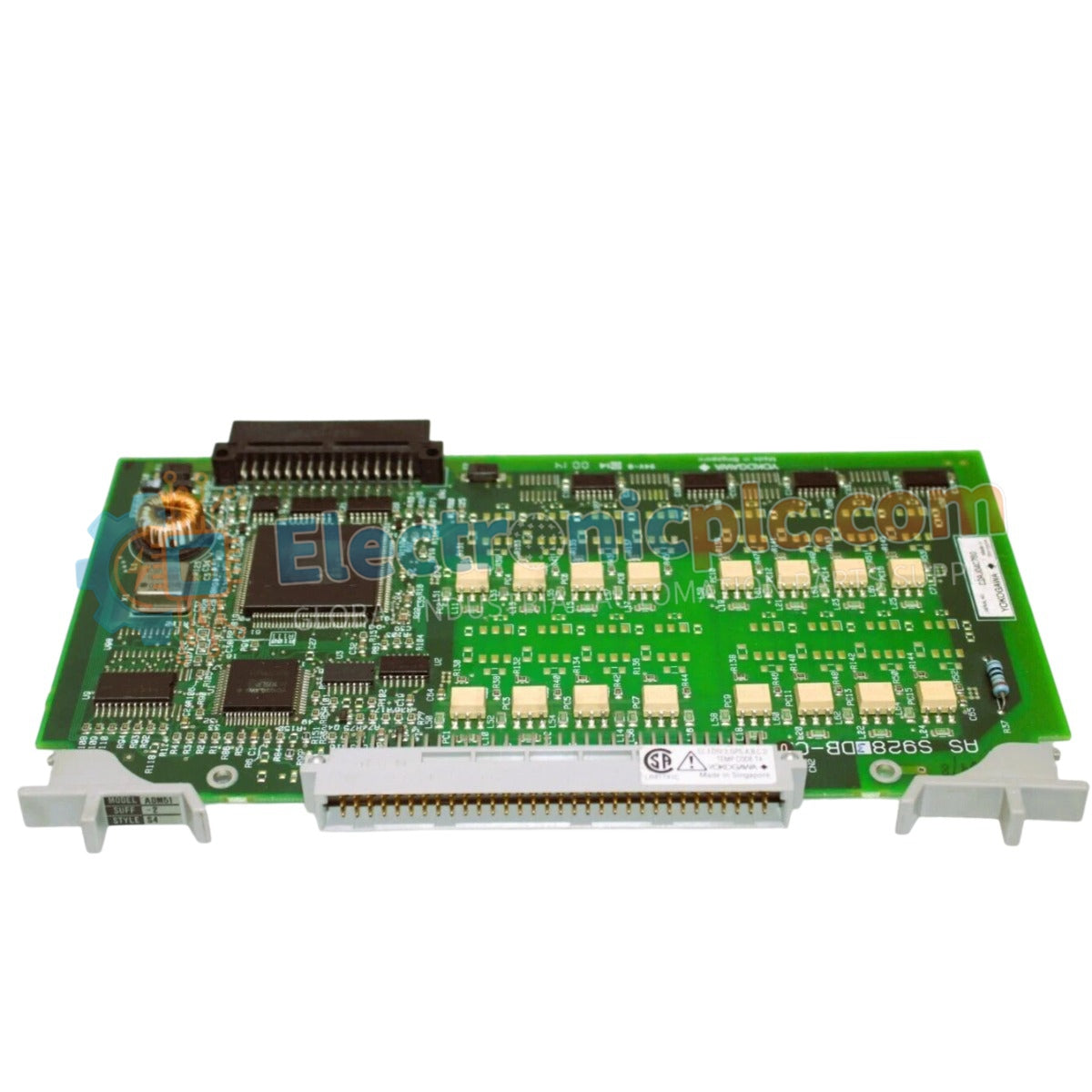
Configured for discrete signal execution in distributed control networks, the Yokogawa ADM51C-2 (ADM51C-2 Contact Output Module) provides direct physical switching control to field-mounted relays, contactors, and solenoid valves. The ADM51C-2 serves as the primary output module utilized to execute discrete command sequences across Yokogawa control system platforms.
The ADM51C-2 is categorized under the style S2 hardware revision, providing an 8-channel independent output configuration within a standardized 16-slot module footprint. This designation indicates high-density output capabilities optimized for modular control cabinets.
| Parameter | Specification |
|---|---|
| Model | ADM51C-2 |
| Brand | Yokogawa |
| Origin | Japan |
| Weight | 0.14 kg |
| Dimensions | Standard DIN-rail mount form factor |
| Operating Temp | 0 to 60 deg C |
| Power Consumption | 3 W (typical) |
| Output Channels | 8 independent channels |
| Logic Levels | 0 V / 5 V DC |
The ADM51C-2 integrates into the DCS architecture to provide robust channel-to-channel isolation. This electrical design effectively decouples control-side logic from field-side switching circuits, preventing backplane bus communication errors resulting from field-induced voltage spikes or ground loops. Furthermore, the module ensures deterministic signal execution, maintaining precise timing for 0 V and 5 V DC logic-based actuation across the distributed network.
Q: Does the module support hot-swapping during normal system operation?
A: No, the module requires the de-energization of the relevant control loop and the isolation of the terminal block before removal to prevent localized backplane transients.
Q: What is the maximum switching frequency for the contact closures?
A: The switching frequency is limited by the mechanical response time of the integrated relays; refer to the load-specific derating curves for high-duty cycle applications.


