My Cart
0 items
Genuine Automation Parts | Worldwide Express Delivery | 12-Month Warranty — [GET A QUOTE]

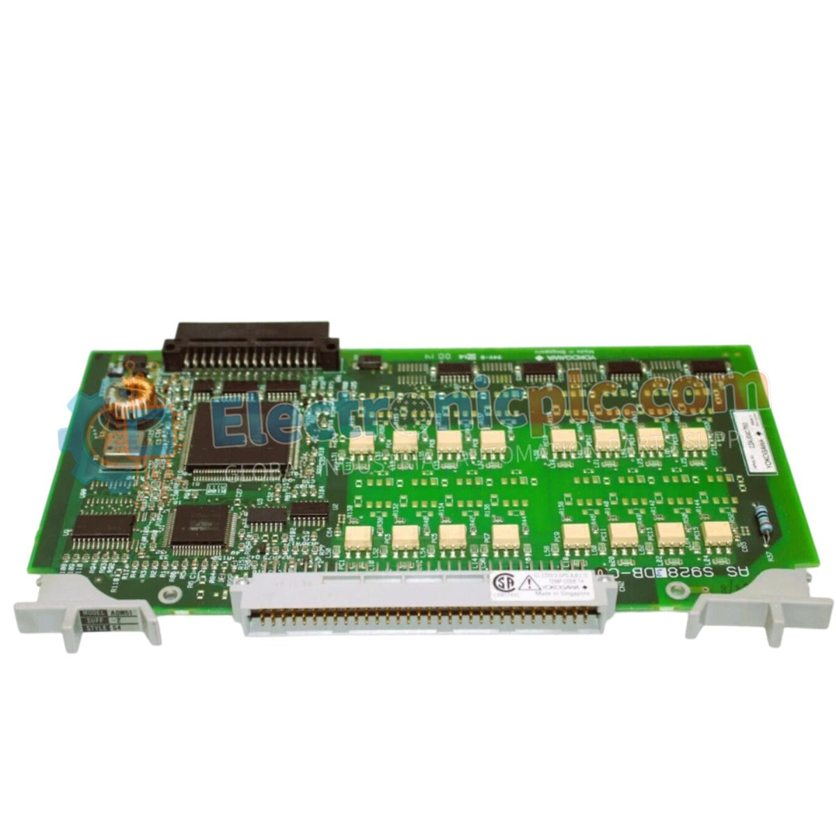
Configured for precision signal acquisition in process control platforms, the Yokogawa ADM52C-2/CE1 (ADM52C Analog Input Module) provides direct physical/electrical execution of 8-channel voltage and current signal conversion.
Availability: In stock
Reliable Worldwide Delivery
30-Day Money-Back Guarantee
Need more details? Read our fullShipping PolicyandRefund Policy.


Configured for precision signal acquisition in process control platforms, the Yokogawa ADM52C-2/CE1 (ADM52C Analog Input Module) provides direct physical/electrical execution of 8-channel voltage and current signal conversion.
| Parameter | Specification |
|---|---|
| Model | ADM52C-2/CE1 |
| Brand | Yokogawa |
| Origin | Japan |
| Weight | 0.5 kg |
| Dimensions | 130 mm x 90 mm x 100 mm |
| Operating Temp | -20 deg C to 60 deg C |
| Power Consumption | 5 W |
| Input Channels | 8 analog |
| Input Impedance | 250 Ohm (Current) / 10 MOhm (Voltage) |
| Accuracy | +/- 0.1% (Current) / +/- 0.2% (Voltage) |
| Sampling Rate | 100 ms per channel |
The ADM52C-2/CE1 utilizes isolated current inputs to mitigate the impact of ground potential differences across the process control loop. Integration within DCS racks requires adherence to standard impedance matching; current loops are terminated via a 250 Ohm burden resistor to satisfy 4-20 mA HART loop protocol requirements. Channel-to-channel isolation is maintained to prevent common-mode voltage transfer between sensors. Users should monitor signal integrity when deploying 0-10 V inputs, as the 10 MOhm high-impedance state makes these channels susceptible to induced noise from nearby high-frequency power cabling.
Q: Can the 24 VDC power input fluctuate without affecting measurement precision?
A: The module is rated for 24 VDC +/- 20%. Excursions outside this range may introduce nonlinearity in the 16-bit A/D conversion process, potentially exceeding the specified +/- 0.1% or +/- 0.2% accuracy thresholds.
Q: Are the current and voltage inputs hot-swappable during active system control?
A: The module is not designed for hot-swapping. Before physical removal or insertion into the DIN rail or panel, verify that the local rack power has been de-energized to prevent arcing at the backplane interface.


