
My Cart
0 items
Genuine Automation Parts | Worldwide Express Delivery | 12-Month Warranty — [GET A QUOTE]

Configured for analog signal termination in CENTUM VP control architectures, the YOKOGAWA AED5D-01 (AED5D Terminal Board) provides direct physical/electrical execution for field instrumentation interfacing. This component processes 16 input/output channels via secure M4...
Availability: In stock
Reliable Worldwide Delivery
30-Day Money-Back Guarantee
Need more details? Read our fullShipping PolicyandRefund Policy.


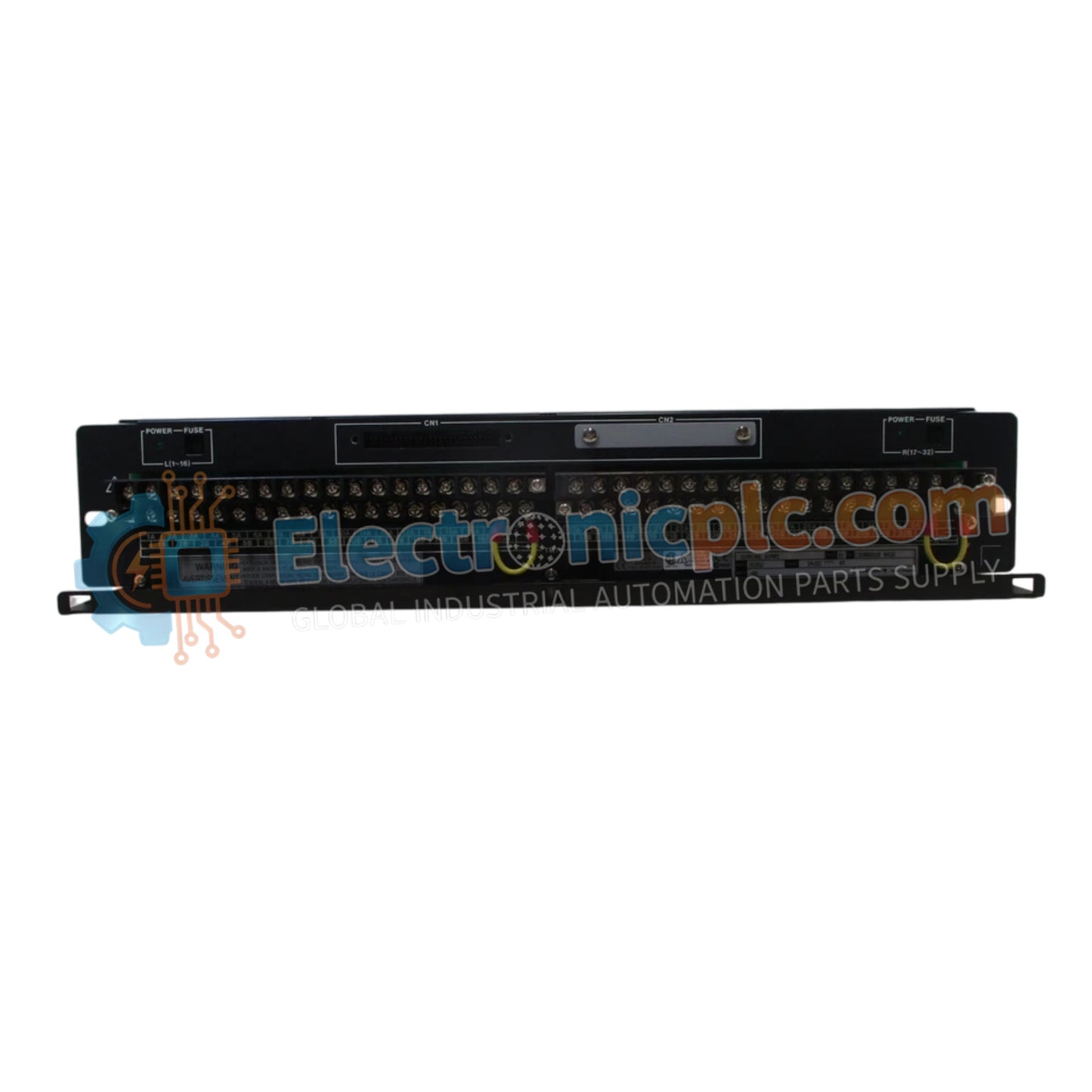
Configured for analog signal termination in CENTUM VP control architectures, the YOKOGAWA AED5D-01 (AED5D Terminal Board) provides direct physical/electrical execution for field instrumentation interfacing. This component processes 16 input/output channels via secure M4 screw terminals, serving as the interface bridge between field wiring and system-side KS1 cabling.
| Parameter | Specification |
| Model | AED5D-01 |
| Brand | YOKOGAWA |
| Origin | Japan |
| Weight | 1.5 kg |
| Dimensions | 482.6 mm x 465.1 mm x 440 mm |
| Operating Temp | Industrial Standard |
| Power Rating | 4 A, 24 V DC |
| I/O Channels | 16 |
| Terminal Type | M4 screw |
The AED5D-01 is engineered to maintain high loop integrity within distributed control networks. It supports 4-20 mA HART loop protocol signal transmission through high-conductivity copper paths, ensuring minimal contact resistance. The board incorporates built-in surge absorbers to suppress transient voltages, protecting sensitive DCS input cards from electrical surges commonly found in long-distance field cabling. Galvanic isolation and dielectric strength are verified to 500 V AC for 1 minute, preventing cross-channel interference.
Q: Does the AED5D-01 provide intrinsic safety (Ex i) barriers for hazardous locations?
A: No, the AED5D-01 is a standard terminal board and does not include intrinsic safety barriers. It is designed for use in non-hazardous environments or requires external barriers if connected to field instruments in explosive zones.
Q: Can the KS1 cable be hot-swapped while the field instruments are powered?
A: While the KS1 interface is robust, it is recommended to isolate power from the loop before connecting or disconnecting the cable to prevent electrical transients from affecting the DCS I/O module or the field transmitter.
Ensure the 19-inch rack is grounded to the primary cabinet ground busbar to maintain an effective reference for the surge protection circuitry.
Terminate all field wires using M4 ring-type lugs. Ensure screws are tightened to the manufacturer's specified torque to prevent high-resistance connections or intermittent signal drops.
Route field wiring and the KS1 signal cable in separate trays or conduits to avoid induction from high-voltage AC cables, which can degrade analog signal accuracy.
Verify the insulation resistance across terminals periodically; readings should remain above 100 MOhm at 500 V DC to ensure long-term reliability.
In environments with high vibration, apply thread-locking compound (non-conductive) to M4 terminal screws or perform periodic tension inspections to ensure connectivity integrity.


