
My Cart
0 items
Genuine Automation Parts | Worldwide Express Delivery | 12-Month Warranty — [GET A QUOTE]

Configured for safety-critical signal processing in ProSafe-SLS platforms, the Yokogawa AI-917-00 (AI-917-00 Analog Input Module) provides direct physical/electrical execution of 4 analog inputs and 4 logic pulse outputs.
Availability: Low stock: 99 left
Reliable Worldwide Delivery
30-Day Money-Back Guarantee
Need more details? Read our fullShipping PolicyandRefund Policy.


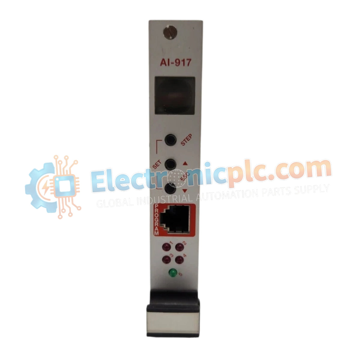
Configured for safety-critical signal processing in ProSafe-SLS platforms, the Yokogawa AI-917-00 (AI-917-00 Analog Input Module) provides direct physical/electrical execution of 4 analog inputs and 4 logic pulse outputs.
| Parameter | Specification |
|---|---|
| Model | AI-917-00 |
| Brand | Yokogawa |
| Origin | Japan |
| Weight | 0.4 kg |
| Dimensions | 96 mm x 35 mm x 130 mm |
| Operating Temp | -40 to +80 deg C |
| Power Consumption | 50 mA (24 VDC) |
| Analog Inputs | 4 (0-20 mA, 4-20 mA, 0-10 V, -10 to +10 V) |
| Logic Pulse Outputs | 4 (Pulse or Continuous) |
| Accuracy | +/- 0.1% of span |
This module is designed for implementation in SIL 4 capable architectures, ensuring fail-safe state execution within the ProSafe-SLS safety instrumented system. The design incorporates advanced galvanic isolation to maintain the electrical integrity of safety-critical loops, preventing common-mode failure propagation. Every internal logic state is governed by the application program, ensuring that in the event of an input threshold violation, the module transitions field devices to the pre-defined safe state. The 2 A current capacity on the logic pulse outputs facilitates direct actuation or signaling for safety-critical equipment, providing the necessary drive strength while maintaining the required safety integrity levels.
Q: Can the analog input range be reconfigured for individual channels via software?
A: Yes, the functionality of the AI-917-00 is programmable through the application environment. Each of the four analog inputs can be configured to support the specified current or voltage ranges based on the loaded safety logic.
Q: Are the logic pulse outputs isolated from the analog input circuits?
A: The module architecture utilizes electrical isolation barriers to separate the input sensing circuits from the pulse output drivers, ensuring that field faults on the input side do not compromise the integrity of the safety outputs.


