My Cart
0 items
Genuine Automation Parts | Worldwide Express Delivery | 12-Month Warranty — [GET A QUOTE]

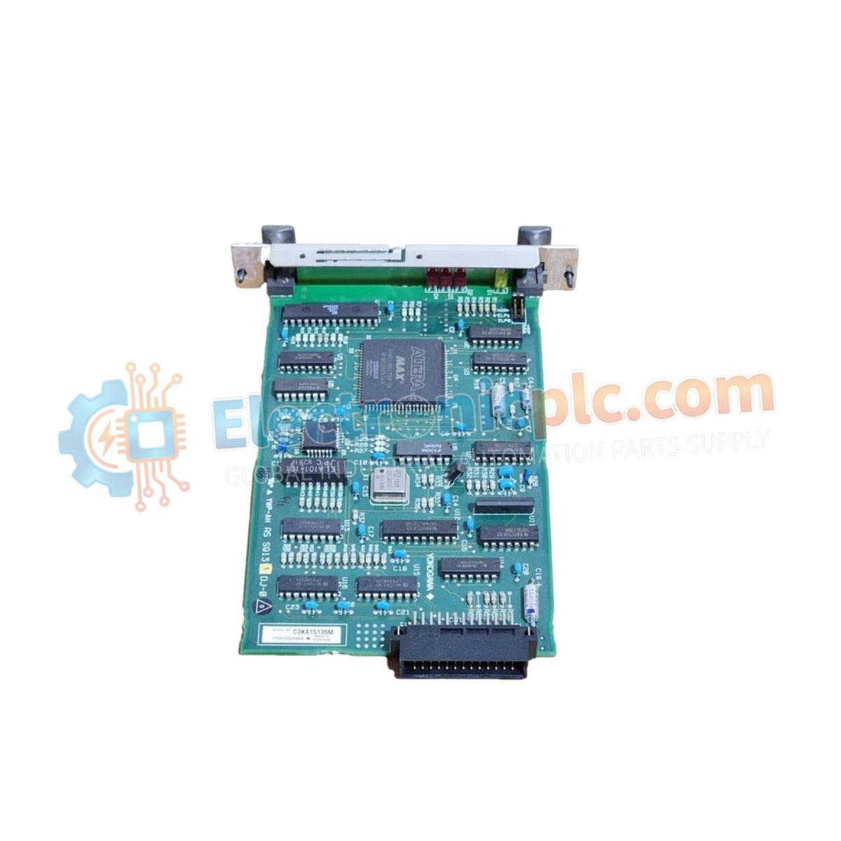
Configured for multi-protocol data exchange in process control architectures, the YOKOGAWA AIP171 S2 (AIP171 Transceiver Control Module) provides direct physical and electrical execution of serial and Ethernet communication tasks.
Availability: Low stock: 99 left
Reliable Worldwide Delivery
30-Day Money-Back Guarantee
Need more details? Read our fullShipping PolicyandRefund Policy.


Configured for multi-protocol data exchange in process control architectures, the YOKOGAWA AIP171 S2 (AIP171 Transceiver Control Module) provides direct physical and electrical execution of serial and Ethernet communication tasks.
| Parameter | Specification |
|---|---|
| Model | AIP171 S2 |
| Brand | YOKOGAWA |
| Origin | Janpan |
| Weight | 0.2 kg |
| Dimensions | 3.2 cm x 12 cm x 13 cm |
| Operating Temp | 0 to 50 deg C |
| Power Consumption | 20 W |
| Communication Interfaces | RS-485, RS-232, Ethernet |
| Supported Protocols | TCP/IP, SPI, I2C, UART |
| Frequency Range | 100 MHz to 6 GHz |
The AIP171 S2 design utilizes channel-to-channel isolation to decouple sensitive transceiver circuitry from high-energy backplane transients. This isolation architecture prevents ground potential shifts from propagating across the serial interface when connected to external devices. In multi-protocol environments, the module performs real-time signal conditioning to maintain data integrity across TCP/IP and UART segments, ensuring that communication timing remains consistent with the deterministic requirements of the host control station.
Q: Does the module support hot-swapping under full backplane load?
A: No. The AIP171 S2 is not hot-swap compatible. Power must be removed from the module and the associated backplane segment before physical extraction or insertion to prevent damage to the communication controllers.
Q: How should the shield be terminated for the RS-485 interface to maintain signal integrity?
A: The shield must be connected to a clean functional earth at one point only to avoid ground loops. Ensure that the impedance of the termination matches the cable characteristics for the specified transmission frequency to mitigate signal reflections.


